
On this page
In short
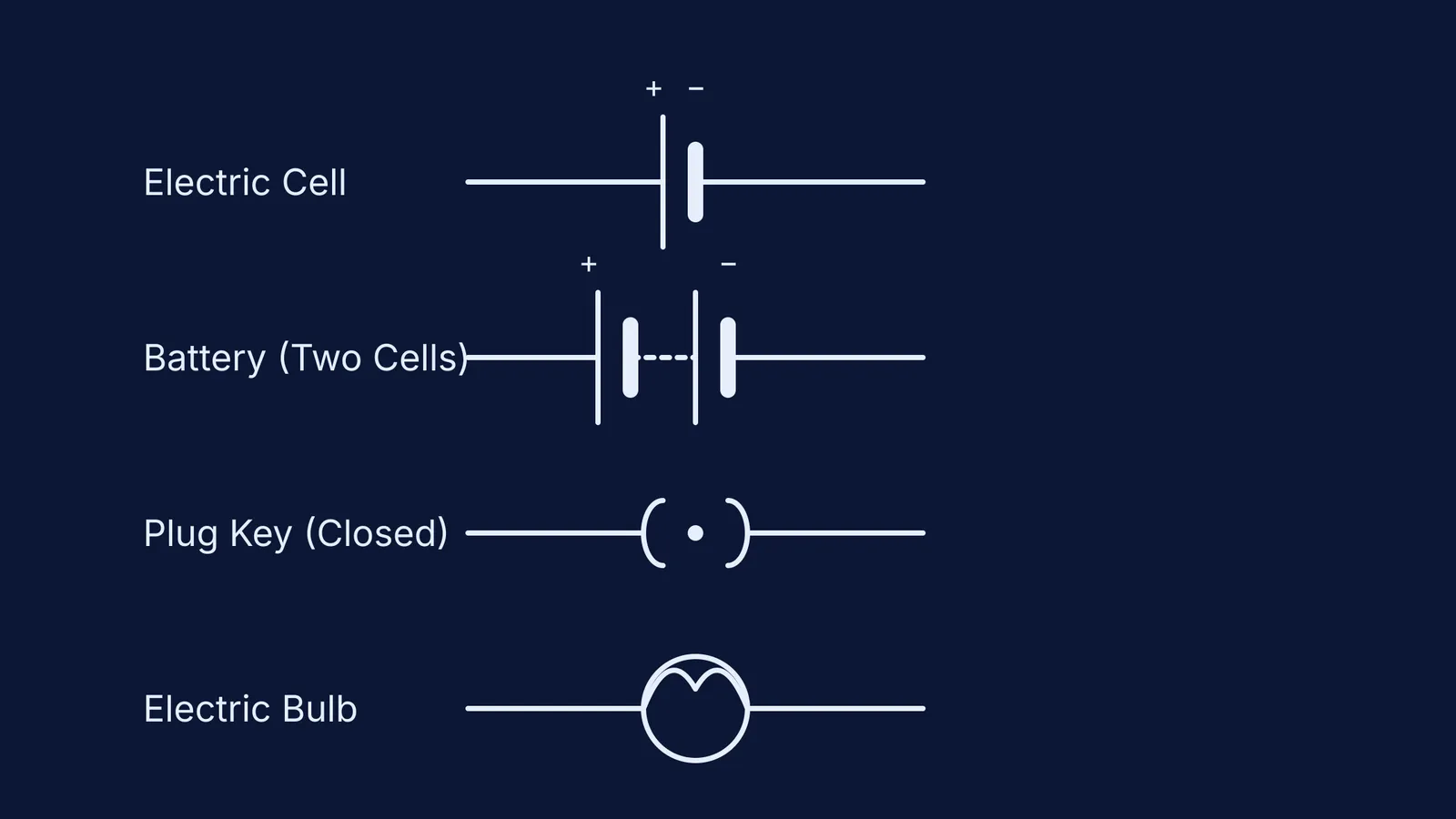
The standard circuit symbol for an electric cell is a long line (positive terminal) and a short, thick line (negative terminal). A battery is drawn as two or more cells linked end-to-end. An electric bulb is a circle with a cross or a filament curve inside, and a switch (plug key) is drawn as `( )` when open and `( . )` when closed. We use these standard symbols to map out electrical paths universally.
When scientists first started experimenting with electricity, they drew realistic pictures of glass jars, metal plates, and wires to record their setups. As circuits grew more complex, these sketches became impossible to read and copy. Today, we use standard circuit symbols to map out electrical paths.
These shapes are governed globally by the International Electrotechnical Commission (IEC 60617 standard), which favours simple, minimalist geometric shapes over detailed pictures. In India, textbooks such as the NCERT Class 10 Science textbook strictly follow these conventions in their electricity chapters. Using standard symbols means that an engineer in Bengaluru can instantly read a schematic drawn in Berlin.
If you are learning how electricity flows and need to visualise the rules behind these lines, the Fermi Concept Library holds every concept in physics — including circuit conventions — each with its own lesson and its place in the map.
What are the symbols of electric components?
When you look at a standard circuit diagram, you are seeing a simplified map. The most common symbols you will encounter include:
Connecting wire: A straight line. When wires cross without joining, one line jumps over the other in a small semi-circle. When they join, a solid dot is placed at the intersection.
Electric bulb (lamp): A circle with a cross inside it, or a circle containing an "M" shaped curve representing the tungsten filament. (See Why a bulb glows instantly if drift velocity is so small for more on how the bulb actually lights up).
Resistor: A simple zig-zag line. This represents a component that opposes the flow of current.
What is the symbol of an electric cell?
The electric cell is the power source for a basic circuit, providing the potential difference that pushes electrons through the wires. Its symbol is composed of two parallel vertical lines of unequal length.
The long, thin vertical line represents the positive terminal (+).
The shorter, thicker vertical line represents the negative terminal (−).
By convention, electric current is drawn as flowing from the positive terminal to the negative terminal through the external circuit. This is the opposite of the actual flow of electrons, which are negatively charged and move from the negative to the positive terminal.
What is the difference between a cell and a battery?
People often use the words "cell" and "battery" interchangeably in daily life, but in physics, they mean different things. A cell is a single unit that generates electrical energy. A battery is a combination of two or more cells connected together to provide a higher total voltage.
The symbol for a battery is simply a series of cell symbols linked end-to-end. The long line of the first cell is followed by a short line, which connects via a dotted line to the long line of the next cell, and so on. The crucial rule when drawing or connecting a battery is that the positive terminal of one cell must always connect to the negative terminal of the next.
If you make a mistake in a circuit problem and cannot work out why your total voltage is wrong, bringing your attempt to the Fermi Problem Library gives you a step-by-step solver that explains the reasoning behind loop equations rather than just printing the final answer.
How do you draw a switch or plug key?
A switch controls the flow of current. When the switch is open, the circuit is broken; when it is closed, the circuit is complete.
In Indian diagrams, you will frequently see a "plug key" symbol, which represents the physical brass plug keys used in school laboratories:
Plug key (open): Drawn as two parentheses with a gap between them `( )`. No current can flow.
Plug key (closed): Drawn as two parentheses with a heavy dot in the centre `( . )`. The dot represents the brass plug inserted into the gap, allowing current to pass.
In international schematics, a switch is often drawn as a straight line breaking away at an angle from the main wire, acting like a drawbridge that can open or close.
Where do the ammeter and voltmeter go in a circuit?
To measure what is happening in your circuit, you will need instruments. Their symbols are simple circles containing a letter, with + and − signs marked at the connecting wires.
Ammeter: A circle with the letter "A" inside. It measures electric current and must always be connected in series with the component, because current is the same along a single path.
Voltmeter: A circle with the letter "V" inside. It measures the potential difference (voltage) and must always be connected in parallel across the component you are measuring.
Drawing these symbols correctly is the first step in solving advanced problems, such as calculating Induced emf in a loop near a long wire or running an RC circuit simulation.