

On this page
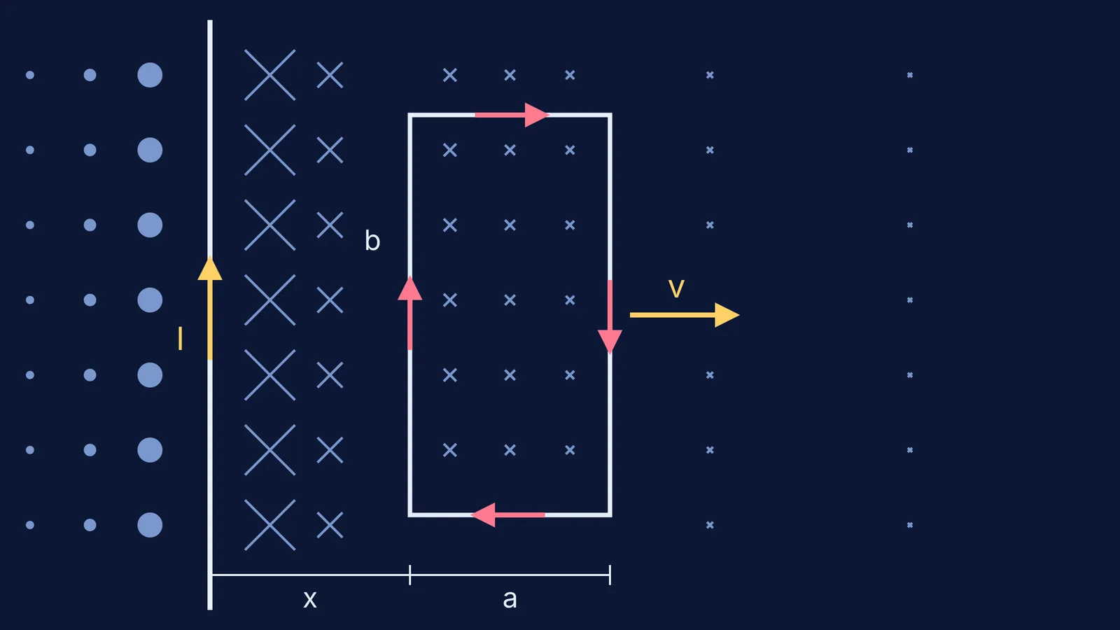
A long straight wire carries a steady current I. Next to it, in the same plane, sits a rectangular loop. Side b runs parallel to the wire, side a points away from it, and the near edge is a distance x from the wire. Pull the loop away, or change I, and a current flows in the loop. It all comes down to one short integral.
Why can't you just use flux = BA here?
The magnetic field of a long straight wire is B = μ0I/(2πr), where r is the distance from the wire (OpenStax University Physics Volume 2, section 12.2). The constant μ0 is 4π × 10⁻⁷ T·m/A (same source). Because B falls off as 1/r, the near edge of the loop sits in a stronger field than the far edge, so you have to slice the loop up.
How do you find the flux through the loop?
Cut the loop into thin strips parallel to the wire. A strip at distance r has width dr and length b. Across one strip B is effectively constant, so its flux is dΦ = (μ0I/2πr) b dr. Add up the strips from r = x to r = x + a:
Φ = (μ0Ib/2π) ln((x + a)/x)
Only b sits outside the log; a sits inside it. The flux depends on x and I, so changing either one makes an emf.
What is the induced emf in a loop moving away from the wire?
Faraday's law says the induced emf is minus the rate of change of flux, ε = −N dΦ/dt (OpenStax University Physics Volume 2, section 13.1). Here N = 1, I is constant and x grows at the rate dx/dt = v. Differentiating the log gives dΦ/dt = (μ0Ib/2π)[1/(x + a) − 1/x]v, so the size of the emf is:
ε = μ0Iabv / [2πx(x + a)]
Check it with motional emf. A rod of length l moving at speed v through a field B has emf Blv (OpenStax University Physics Volume 2, section 13.3). The near side gives μ0Ibv/(2πx) and the far side gives μ0Ibv/(2π(x + a)). They oppose each other, so the net emf is their difference: the same answer. The top and bottom sides move along their own length and add nothing, as with a rod sliding on rails.
Now the direction. The flux into the page is falling, so the induced current flows clockwise to replace it. The near side then carries current parallel to the wire's and is attracted; the far side is repelled, but more weakly. The net pull back towards the wire is Lenz's law opposing the motion. More practice: finding the induced current direction with Lenz's law.
How big is the emf in a worked example?
Take I = 10 A, a = 10 cm, b = 20 cm, x = 10 cm, v = 2 m/s and loop resistance R = 0.5 Ω. Using μ0/2π = 2 × 10⁻⁷ T·m/A (OpenStax section 12.2):
Flux: Φ = 2 × 10⁻⁷ × 10 × 0.2 × ln 2 ≈ 2.77 × 10⁻⁷ Wb.
Emf: ε = (2 × 10⁻⁷ × 10 × 0.1 × 0.2 × 2) / (0.1 × 0.2) = 4 μV.
Current: i = ε/R = 8 μA, clockwise.
What if the current changes and the loop stays still?
Write Φ = MI with M = (μ0b/2π) ln((x + a)/x), where M is the mutual inductance, so ε = −M dI/dt (OpenStax section 14.1). With the same loop, M = 2 × 10⁻⁷ × 0.2 × ln 2 ≈ 2.77 × 10⁻⁸ H. If I rises at 50 A/s, ε ≈ 1.39 μV and i ≈ 2.8 μA. This time the current is anticlockwise, because the flux into the page is growing.
If both I and x change, use the product rule: dΦ/dt = (μ0b/2π)[ln((x + a)/x) dI/dt − Iav/(x(x + a))], and ε = −dΦ/dt. The total charge that flows is ΔΦ/R, however fast the change; see charge flow from a change in flux.
Which mistakes cost marks on this problem?
Using B at the centre of the loop (B varies as 1/r). With I = 10 A, a = 10 cm, b = 20 cm and x = 1 cm, the exact flux is about 9.6 × 10⁻⁷ Wb, but B at the centre times the area gives about 6.7 × 10⁻⁷ Wb, roughly 30% too low.
Swapping a and b: the side parallel to the wire goes outside the log.
Adding the two side emfs instead of subtracting them.
Forgetting that a loop moving parallel to the wire has zero emf, because x and the flux don't change.
If the 1/r field itself feels shaky, the Fermi Concept Library has a lesson for each concept in physics. If the signs keep going wrong, the Fermi Problem Library has worked problems with a step-by-step solver that explains the reasoning rather than just printing an answer.
Try the worked example again with x = 20 cm. You should get an emf one third the size, about 1.3 μV.


