
On this page
Put a 555 timer, two resistors and a capacitor on a breadboard and an LED blinks on its own, no code needed. It is a classic electronics project and a tidy piece of physics: the blink rate comes straight from the RC charging curve. Hans Camenzind designed the chip in 1971 and Signetics first marketed it in 1972, according to the history of the 555 timer IC.
What is inside a 555 timer?
Each 555 has a trigger level of about one-third of the supply voltage and a threshold level of about two-thirds, according to the Texas Instruments NE555 datasheet.
Inside, two comparators watch those levels and a flip-flop remembers which fired last. The pins a blinker uses:
Pin 1 (GND) to ground; pins 8 (VCC) and 4 (RESET) to the supply.
Pin 2 (TRIG): below one-third of the supply, the output goes high.
Pin 6 (THRES): above two-thirds, the output goes low.
Pin 7 (DISCH) shorts to ground while the output is low.
Pin 3 (OUT) drives the LED; pin 5 (CONT) gets 0.01 µF to ground.
The datasheet specifies the NE555 for 5 V to 15 V supplies.
How does a 555 timer work in astable mode?
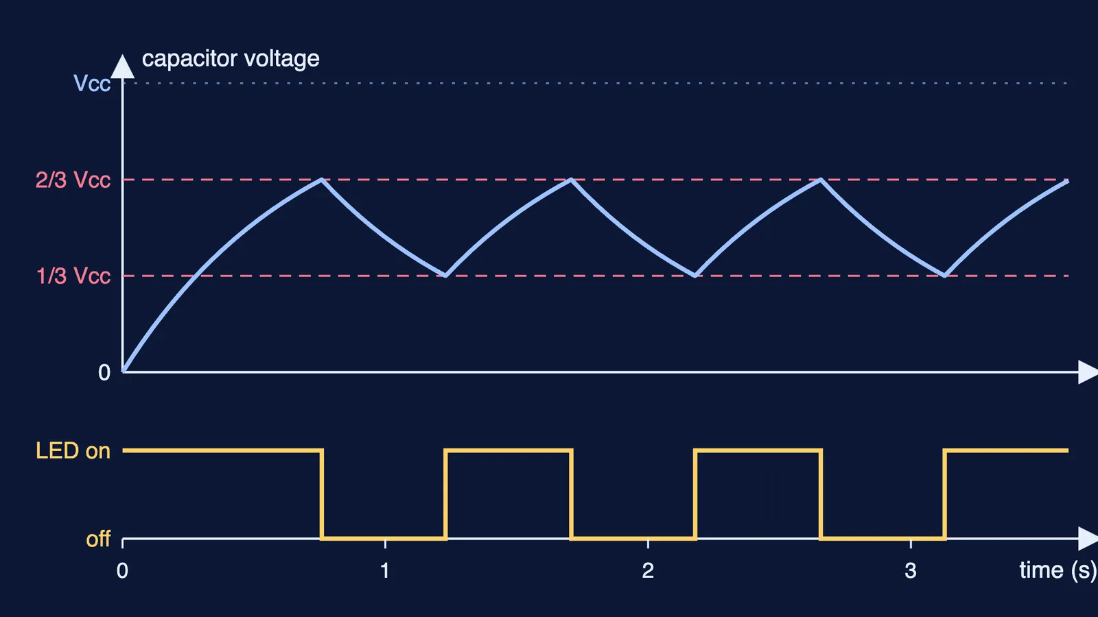
Resistor RA runs from the supply to pin 7, RB from pin 7 to pins 2 and 6 joined together, and capacitor C from there to ground. The TI datasheet says C charges through RA and RB, discharges through RB only, and swings between about 0.67 and 0.33 of the supply.
At switch-on C is empty, below one-third, so the output is high and pin 7 is open.
C charges through RA plus RB. At two-thirds, the output goes low and pin 7 grounds.
C empties through RB into pin 7. At one-third, the output goes high, pin 7 opens, and step 2 begins again.
Where does the 0.693 in the 555 formula come from?
While charging, the capacitor heads towards the full supply with time constant (RA + RB)C. The gap between it and the supply starts at two-thirds of the supply and ends at one-third: it halves. An exponential halves in one time constant times ln 2, and ln 2 is about 0.693.
Discharging through RB alone, the voltage falls from two-thirds to one-third, halving again. So the high time is 0.693(RA + RB)C and the low time is 0.693 RB C, exactly the formulas in the TI datasheet. Both levels are fractions of the supply, so the supply cancels: TI notes that frequency and duty cycle do not depend on it.
The very first high time is longer, because C starts from zero: the gap shrinks by a factor of 3, which takes ln 3, about 1.1 time constants. For more practice, see the time constant of an RC circuit with two resistors and when a discharging capacitor's energy becomes half.
Worked example: a 555 blinking LED at about once a second
Take a 9 V battery, an NE555, RA = 1 kΩ, RB = 68 kΩ and C = 10 µF. Using the TI datasheet formulas:
High time: 0.693 × 69 kΩ × 10 µF = 0.693 × 0.69 s, about 0.48 s.
Low time: 0.693 × 68 kΩ × 10 µF, about 0.47 s.
Period about 0.95 s; check: 1.44 ÷ (137 kΩ × 10 µF) is about 1.05 Hz.
Duty cycle: 69 ÷ 137, about 50.4% on.
First flash: 1.1 × 0.69 s, about 0.76 s.
The output does not reach the full supply. The datasheet's graph of output drop against current shows a typical drop of about 1.4 V at 15 mA and 25 °C, so on 9 V expect about 7.6 V. If your LED's datasheet says 2 V at 15 mA, the series resistor is (7.6 − 2) ÷ 0.015, about 373 Ω; take the next standard value up, 390 Ω, for roughly 14 mA. The full method is in how to calculate the resistor for an LED.
Why is my 555 LED not blinking?
Check these against the TI datasheet first:
Pin 4 floating. TI says to tie RESET to the supply when unused, to prevent false triggering.
Pins 2 and 6 not joined.
Electrolytic capacitor reversed: the striped leg goes to ground.
LED backwards, or no series resistor.
LED looks steadily on: with 10 nF instead of 10 µF the formula gives about 1,050 Hz, far too fast to see.
Supply outside the NE555's 5 V to 15 V range.
If exponential charging still feels like symbols on a page, Fermi's AI tutor can work through it with you, drawing the figure and checking your understanding as it goes. The Fermi Simulation Lab has interactive simulations for ideas that are easier to see than to read.
Build it, write down your predicted period, then time 20 blinks and divide by 20: the gap between the two is your next physics question.