On this page
When electric current flows through a thin conductor placed in a perpendicular magnetic field, charge carriers experience a sideways Lorentz force, F = q(v × B). In 1879, Edwin H. Hall discovered this transverse deflection at Johns Hopkins University, publishing his results in the American Journal of Mathematics. Using very thin gold leaves, Hall proved that magnetic fields act directly on the moving charge carriers rather than merely tugging the metallic lattice.
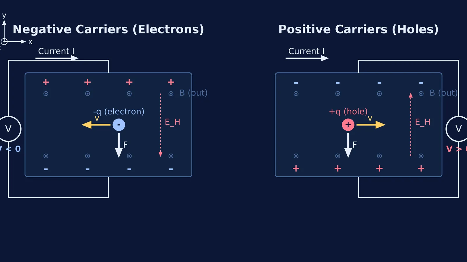
This deflection pushes charges toward one lateral edge until accumulating charge creates a transverse Hall electric field E_H. At steady state, the electrostatic force balances the magnetic force, establishing a measurable Hall voltage V_H across the strip width.
Which side of a conductor charges up in a magnetic field?
Consider a thin rectangular strip lying in the xy-plane. Conventional current I flows along +x, and an external magnetic field B points perpendicular to the surface along +z. Many students intuitively assume that because electrons and holes carry opposite charges, they must deflect toward opposite edges. That assumption overlooks how drift velocity aligns with conventional current.
Why do electrons and holes deflect to the same edge?
Tracking the vector cross-product F = q(v × B) reveals why both carrier types deflect toward the exact same boundary:
Positive holes (q = +e): Holes drift along +x with velocity v = +v_d x̂. The cross-product gives x̂ × ẑ = −ŷ, so F = (+e)(v_d x̂ × B ẑ) = −e v_d B ŷ. The magnetic force pushes holes downward toward the bottom edge (−y).
Negative electrons (q = −e): Electrons drift along −x with velocity v = −v_d x̂. The cross-product gives (−x̂) × ẑ = +ŷ, but multiplying by negative charge introduces another minus sign: F = (−e)(−v_d x̂ × B ẑ) = −e v_d B ŷ. The magnetic force also pushes electrons downward toward the bottom edge (−y).
Because reversing the carrier sign flips both the charge and the drift direction, the two minus signs cancel. You can see how hand-rule errors distort this reasoning in our guide to magnetic force right-hand-rule mistakes.
How does carrier sign flip the Hall voltage polarity?
While both carrier types deflect toward the bottom edge, the sign of the charge accumulating on that edge is reversed:
In electron conduction, negative charges accumulate along the bottom edge, leaving positive donor ions along the top edge. The bottom edge is at a lower electric potential (V_bottom < V_top).
In hole conduction, positive charges accumulate along the bottom edge, leaving negative acceptor ions along the top edge. The bottom edge is at a higher electric potential (V_bottom > V_top).
According to calibration guidelines from the NIST Nanoscale Device Characterization Division, the Hall coefficient R_H = 1 / (n × q) is negative for n-type semiconductors and positive for p-type semiconductors. Measuring the voltage polarity across the width directly identifies majority carriers, as explored in n-type and p-type semiconductor carrier concentration.
How do you calculate the Hall voltage in a semiconductor?
Measurement standards from NIST show that force equilibrium q E_H = q v_d B yields E_H = v_d B. Substituting current density I = n × q × w × t × v_d gives:
V_H = E_H × w = (I × B) / (n × q × t)
The width w cancels out; the Hall voltage depends only on current I, magnetic field B, carrier density n, and thickness t.
Here is a worked example: A semiconductor strip with thickness t = 0.10 mm (1.0 × 10⁻⁴ m) and width w = 5.0 mm carries a current I = 20 mA (2.0 × 10⁻² A) in a perpendicular field B = 0.50 T. The measured voltage difference between bottom and top edges is V_bottom − V_top = +6.25 mV (+6.25 × 10⁻³ V).
Determine carrier type: Because V_bottom > V_top, positive charge accumulated at the bottom edge. The majority carriers are positive holes (p-type).
Calculate carrier density: Rearranging the formula yields n = (I × B) / (q × t × V_H). Substituting the values gives n = (2.0 × 10⁻² A × 0.50 T) / (1.602 × 10⁻¹⁹ C × 1.0 × 10⁻⁴ m × 6.25 × 10⁻³ V) = 1.0 × 10²³ m⁻³ (or 1.0 × 10¹⁷ cm⁻³).
If replaced with an identical n-type strip having equal carrier density, the voltmeter reading flips to −6.25 mV.
Why is interactive simulation the fastest way to master the Hall effect?
Coordinating three mutually perpendicular vector directions on paper strains working memory. In research published in the *American Journal of Physics*, Nobel laureate Carl Wieman, Katherine Perkins, and Wendy Adams (DOI: 10.1119/1.2815365) demonstrated that interactive simulations make unobservable transport dynamics visible, increasing on-topic student discussion during demonstrations and dismantling persistent vector misconceptions.
In the Fermi Simulation Lab, you can explore interactive simulations for ideas that are easier to see than to read, toggling carrier polarity to watch particles deflect and voltmeter needles swing in real time. When preparing for competitive exam problems, the Fermi Problem Library provides worked problems with a step-by-step solver that explains the reasoning rather than printing an answer. To strengthen vector fundamentals further, review our guide to reading electric and magnetic field lines.