
On this page
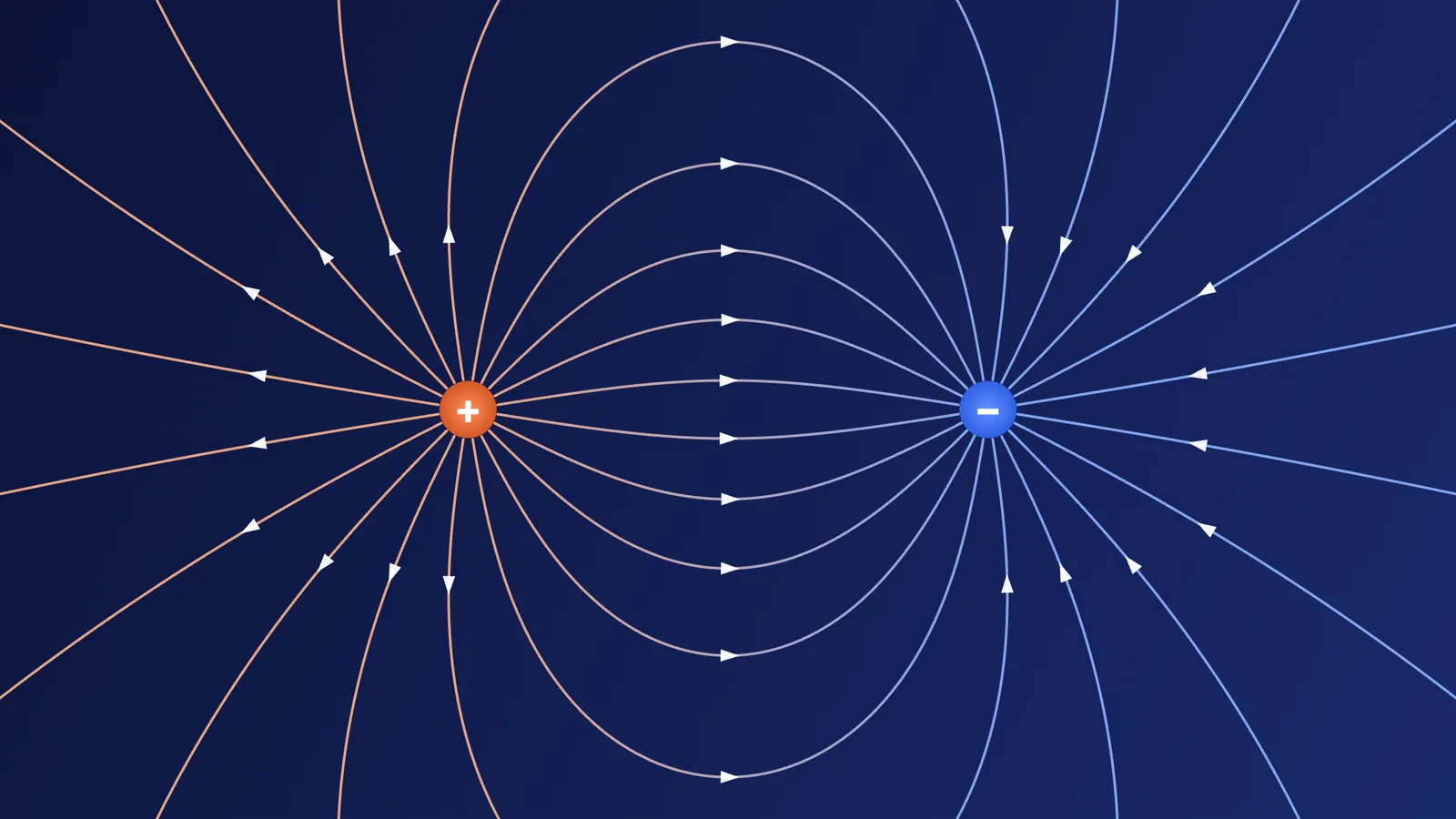
Field-line diagrams are in every electrostatics and magnetism chapter, and they are easy to misread. The trouble is that the picture looks simple, so students rarely stop to ask what each part means.
How well do students understand fields?
Not very well, even after a course. The Conceptual Survey of Electricity and Magnetism, a 32-question test given to more than 5,000 introductory physics students at 30 institutions, found typical pretest scores of 31% in calculus-based courses and 25% in algebra-based ones. After instruction, scores rose only to 47% and 44%.
Part of the problem may be the pictures themselves. In a 1993 paper titled "Confusion by representation", Törnkvist, Pettersson and Tranströmer argued that university students' "diffuse ideas" about force and force field could come from a lack of mastery of the graphical representation of these concepts.
What do field lines actually tell you?
The NCERT Class 12 Physics chapter on electric charges and fields sets out the rules. A field line is "a curve drawn in such a way that the tangent to it at each point is in the direction of the net field at that point." The relative closeness of lines shows where the field is stronger. Electric field lines:
start on positive charges and end on negative charges, or at infinity for a single charge;
are continuous in a charge-free region;
never cross, because the field at a point can only have one direction;
do not form closed loops in electrostatics.
Magnetic field lines differ in one big way: around a magnet or solenoid they form continuous closed loops. NCERT also avoids calling them "lines of force", because in magnetism the field lines do not show the direction of the force on a moving charge.
Five common misreadings, and the fix
"A charge moves along the field line." The field line gives the direction of the electric force, so of the acceleration, not the velocity. A charge that is already moving sideways will cut across lines. Only a charge released from rest on a straight field line follows it.
"The number of lines is physical." You choose how many lines to draw. NCERT points out that it is the relative density in different regions that carries meaning.
"No line drawn means no field." The field exists everywhere between the drawn lines. The lines are a sample, not the whole field.
"Magnetic force points along the field line." The force on a moving charge is F = qv × B, which is perpendicular to both v and B. A charge moving along a magnetic field line feels no magnetic force at all.
"The diagram is the whole picture." Field lines live in three dimensions. A textbook figure shows one flat slice, as NCERT reminds readers.
Worked example: the field of a dipole
Take a charge +q and a charge −q a small distance apart, with +q on the left.
At the midpoint. The field from +q points away from it, to the right. The field from −q points towards it, also to the right. Both point the same way, so the fields add and the net field points from +q to −q.
At a point on the perpendicular bisector. The point is the same distance from both charges, so the two fields have equal magnitude. The field from +q points away from +q, partly up and partly right. The field from −q points towards −q, partly down and partly right. The up and down parts cancel; the right parts add. The net field is parallel to the line joining the charges, pointing from +q towards −q.
Now check the diagram. At that point the field line should run parallel to the dipole axis. If your sketch shows lines curving straight up at the bisector, the sketch is wrong. Doing the vector addition yourself and then comparing with the picture builds both skills at once. For more on combining vectors, see our post on common vector errors in JEE physics.
Using a simulation to check your reading
Static figures cannot answer "what if?" questions, which is where a simulation helps. PhET's free Charges and Fields simulation lets you arrange charges and see the resulting field, and plot equipotential lines. One of its stated learning goals is to predict the field lines for an arrangement of charges and verify the prediction using vector addition. Try this:
Place +q and −q. Predict the field direction at three points, then check.
Make both charges positive. Where is the field zero?
Draw an equipotential line and compare its direction with the field. What angle do they make?
For magnetism, PhET's Magnets and Electromagnets lets you explore how a compass behaves around a bar magnet and build an electromagnet from a battery and a coil.
The Fermi Simulation Lab has interactive simulations for the ideas that are easier to see than to read. For what the research says about learning from simulations, read what interactive simulations are good for.