
On this page
In 1885, three Ganz Works engineers in Budapest patented the pattern electricity still follows to your home. Károly Zipernowsky, Miksa Déri and Ottó Bláthy (the "ZBD" initials) built transformers with a closed iron core and connected them in parallel across a high-voltage line.
What was the ZBD transformer?
The national technical library of the Budapest University of Technology and Economics records that the three engineers developed a new transformer-based power distribution system in 1884-85. On Bláthy's suggestion the transformers had a closed iron core, and in 1885 the three patented them. Péter Asztalos's 1986 paper Centenary of the Transformer says the patent applications were filed in January-March 1885 and covered parallel connection, freely chosen transformer ratios and closed-core transformers.
According to the library's biographies, Zipernowsky (1853-1942) was asked in 1878 to organise Ganz's new department for power-current electricity (Zipernowsky biography). Déri (1854-1938) took part in the experiments and in building the power stations that used the new system (Déri biography). Bláthy (1860-1939) later patented an induction electricity meter in 1889, and the library calls today's household power meters modernised versions of it (Bláthy biography).
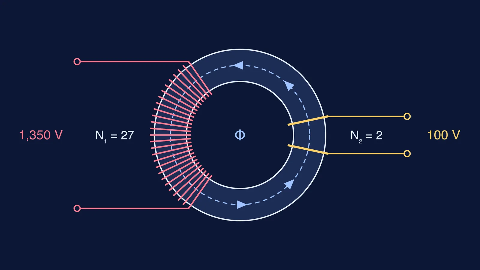
The system went on public show at the 1885 National Exhibition in Budapest, where 75 small shell-type transformers supplied 1,067 incandescent lamps from AC distributed at 1,350 V and 70 Hz (BME library).
Why did a closed iron core matter?
Lucien Gaulard and John Dixon Gibbs's 1882 "secondary generator" had an open iron core, so part of the magnetic path ran through air. It used a fixed 1:1 ratio and fed lamps wired in series. Its voltage was adjusted by moving the core in or out (Wikipedia's history of the transformer, citing Halacsy and Von Fuchs, 1961).
In a closed core, almost all the magnetic flux from the primary coil stays in the iron and passes through the secondary. The BME library describes the result: a small voltage drop, so the terminal voltage hardly depends on the load, and low losses (BME library).
Why did parallel connection make AC practical?
In a series circuit, one current flows through every lamp, so switching one off affects the rest. In parallel, every load sits across the same voltage and can be switched on its own. The ZBD scheme connected its transformers in parallel to the main line. High-ratio transformers kept a 1,400-2,000 V supply network separate from 100 V consumer circuits (BME library).
In 1886, Ganz installed the Rome-Cerchi power station, which the library calls the first site in the world where AC generators were connected in parallel. In 1892, a hydroelectric plant was built at Tivoli, and a 28 km, 5,000 V line carried its power to Rome (BME library). For an earlier long-distance experiment, read how Marcel Deprez proved high-voltage power transmission.
How much power does high voltage save?
Take the exhibition's 1,350 V line and its 1,067 lamps on 75 transformers (BME library) and step down to the 100 V the ZBD system used for consumers. The library does not give the exhibition's lamp voltage, so the 100 V, lamp current and wire resistance are our assumptions.
Turns ratio: Np/Ns = 1,350/100 = 13.5, so a 27-turn primary needs a 2-turn secondary, as in the diagram.
Load: 1,067 ÷ 75 is about 14 lamps per transformer. Assume each draws 0.5 A at 100 V, so the secondary carries 14 × 0.5 = 7 A and the lamps take 700 W.
Primary current: in an ideal transformer, power in equals power out, so Ip = 700 W ÷ 1,350 V ≈ 0.52 A.
Line loss: assume the supply wire has 1 Ω of resistance. At 1,350 V the loss is I²R = 0.52² × 1 ≈ 0.27 W. Sending 700 W at 100 V needs 7 A, so the loss is 7² × 1 = 49 W.
Loss depends on the square of the current, so cutting the current 13.5 times cuts the loss about 180 times (13.5² ≈ 182). For the board-exam version of these formulas, see transformers and AC generators: turns ratio, efficiency and losses. To see why real cores are laminated, read eddy currents explained.
How should you study the transformer for exams?
Write Vs/Vp = Ns/Np and Ip/Is = Ns/Np, and name the assumption behind each: no leakage flux for the first, no power loss for the second.
Sketch an open core and a closed core side by side, and mark where flux escapes into the air.
Explain why house lamps are wired in parallel.
Redo the worked example with a 2,000 V line. You should get a ratio of 20, a primary current of 0.35 A and a loss of about 0.12 W.
If flux paths are hard to picture, try the Fermi Simulation Lab, which has interactive simulations for ideas that are easier to see than to read. If your numbers come out wrong, the Fermi Problem Library has a step-by-step solver that explains the reasoning rather than printing an answer.
That pole-mounted transformer on your street follows an 1885 pattern.