

On this page
If you watch a single-rotor helicopter lift off the ground, the overhead blades spin rapidly in one direction while the cabin beneath them stays pointed steadily forward. That calm stability is not accidental. Without the small, spinning propeller mounted on the tail boom, the helicopter cabin would violently spin in circles opposite to the blades the moment its skids left the tarmac.
Understanding why this happens reveals one of the most direct applications of rotational mechanics in aerospace engineering. Whether you are analysing flight aerodynamics or preparing for rotational dynamics in competitive exams like JEE Main, the helicopter is a classic demonstration of torque, moment arms, and angular momentum.
Why does a helicopter spin without a tail rotor?
The physical root of the problem lies in Newton's third law of motion: every action generates an equal and opposite reaction.
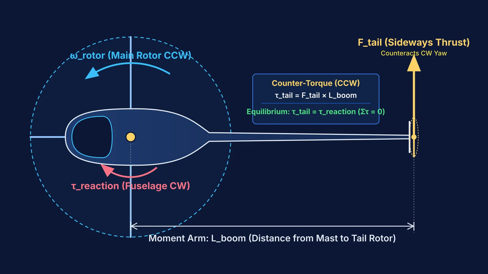
Inside a helicopter, the engine drives a transmission that spins the main rotor shaft. To overcome aerodynamic drag and turn the heavy rotor blades through the air, the engine exerts a continuous rotational torque (τ_engine) on the rotor blades. Because the engine is bolted firmly inside the fuselage, the transmission exerts an equal and opposite reaction torque on the helicopter body itself.
From the perspective of rotational mechanics, this can also be understood through the conservation of angular momentum. Before the engine starts, the helicopter rests motionless on the ground with an initial angular momentum of zero. If no external torque acts on the aircraft as an isolated system, its total angular momentum must remain constant, as documented in OpenStax University Physics:
dL / dt = τ_ext = 0
When the overhead blades spin counter-clockwise, they accumulate large positive angular momentum (L_rotor = I_rotor × ω_rotor). To keep the system's net angular momentum zero in the absence of an external counter-torque, the fuselage must rotate clockwise (L_fuselage = −L_rotor). Because the fuselage has a much larger moment of inertia than the rotor blades, it rotates slower than the blades do, but fast enough to cause immediate loss of control.
How does the tail rotor balance torque and angular momentum?
To prevent the fuselage from spinning, the aircraft needs an external counter-torque. This is the primary function of the antitorque tail rotor.
The tail rotor is mounted vertically at the far end of the tail boom, spinning around a horizontal shaft to produce sideways aerodynamic thrust (F_tail). Because it sits at a distance L_boom from the helicopter's centre of gravity, this lateral thrust creates a restoring torque about the vertical yaw axis:
τ_tail = F_tail × L_boom
In a steady hover, this counter-torque balances the main rotor's reaction torque:
τ_tail = τ_reaction
According to the official FAA Helicopter Flying Handbook, driving this antitorque tail rotor consumes roughly 5% to 15% of the helicopter's total engine power during a stationary hover. Placing the tail rotor at the end of a long boom provides a large moment arm, minimizing the thrust—and therefore the fuel and power—required to neutralize yaw.
Aviation pioneer Igor Sikorsky proved this layout in 1939 with his VS-300 prototype, establishing the single main rotor and tail rotor configuration used across modern aviation, as chronicled in our article on Igor Sikorsky's single-rotor breakthrough.
How do pilots use the pedals to steer?
The tail rotor does not merely keep the aircraft pointed straight; it also acts as the primary yaw control. In the cockpit, the pilot controls the tail rotor using two foot pedals called antitorque pedals.
Unlike an aeroplane's rudder, which deflects existing slipstream airflow, helicopter pedals adjust the blade pitch (angle of attack) of the spinning tail rotor:
Stationary hover: The pilot holds the pedals at a position where tail rotor thrust produces a counter-torque equal to the engine's reaction torque, keeping the nose steady.
Turning against torque: Depressing the pedal to increase blade pitch produces more thrust. The tail rotor torque overcomes the engine reaction torque, swinging the nose toward the turn.
Turning with torque: Easing off the pedal reduces blade pitch, decreasing thrust. The main rotor's reaction torque now exceeds the tail rotor's torque, allowing the fuselage to swing smoothly in the opposite direction.
There is also a secondary aerodynamic effect explained in the FAA Helicopter Flying Handbook: translating tendency. Because the tail rotor pushes sideways to counteract torque, the entire helicopter tends to drift sideways in the direction of the tail thrust. Designers and pilots compensate for this by tilting the main rotor mast slightly in the opposite direction.
How do you calculate tail rotor thrust in hover?
To see how rotational equilibrium works in practice, consider a typical utility helicopter in a stationary hover, using aerodynamic principles from the FAA Helicopter Flying Handbook.
Problem: A light utility helicopter delivers 300 kW of engine power to its main rotor, which rotates at 400 RPM. The tail rotor is mounted on a tail boom 6.0 metres behind the main rotor mast. What horizontal thrust must the tail rotor produce to keep the helicopter from spinning?
Calculate the angular velocity of the main rotor (ω):
ω = (400 × 2 × π) / 60 ≈ 41.89 rad/s
Determine the main rotor torque (τ):
Using the relationship between mechanical power and rotational torque (P = τ × ω): τ = P / ω = 300,000 W / 41.89 rad/s ≈ 7,162 N·m
Calculate the required tail rotor thrust (F_tail):
In a steady hover, the counter-torque produced by the tail rotor must equal the torque of the main rotor: τ_tail = F_tail × L_boom = 7,162 N·m F_tail = 7,162 N·m / 6.0 m ≈ 1,194 N
To maintain heading, the tail rotor must generate approximately 1,194 N of sideways force—equivalent to the weight of about 122 kg—simply to balance the main rotor's torque.
How do you solve rotational equilibrium questions in JEE physics?
Rotational equilibrium problems frequently appear in JEE Main and Advanced, often presented as rotating platforms, hinged rods, or coupled spinning discs. When tackling these questions, use this structured four-step framework:
Define the isolated system: Identify whether the question concerns an isolated body where total angular momentum is conserved (dL / dt = 0), or a system in static equilibrium where net external torque is zero (Στ = 0).
Choose a convenient pivot point: Selecting the point of rotation or the centre of mass eliminates unknown bearing reaction forces. Remember the formal definition of calculating torque with vectors where τ = r × F.
Separate internal reactions from external torques: If an internal motor accelerates one component, apply Newton's third law to write equal and opposite torques for each connected part.
Solve for the balancing force: Equate opposing moments (Στ_clockwise = Στ_counterclockwise) to find the required balancing thrust or normal force.
In the Fermi Simulation Lab, you can explore interactive simulations for ideas that are easier to see than to read, such as varying moment arms and observing how rotational equilibrium responds. For multi-body rotation problems, the Fermi Problem Library provides worked problems with a step-by-step solver that explains the reasoning rather than printing an answer.


