
On this page
A voltmeter connected across a connecting wire in a circuit diagram reads zero. It is a classic trap in Class 12 current electricity and JEE Main because it feels wrong: current flows through that wire, so surely there is a voltage? There is not, and seeing why makes many circuit problems easier.
What does a voltmeter read across a connecting wire?
A voltmeter measures the potential difference between the two points its leads touch. OpenStax University Physics notes that a voltmeter is connected in parallel with whatever device it is measuring, because objects in parallel experience the same potential difference.
Resistance is defined as R = V/I, the potential difference across a conductor divided by the current through it (OpenStax, Resistivity and Resistance). Rearranged, the potential difference across any conductor is V = IR.
In a circuit diagram, a connecting wire is ideal: its resistance is taken as zero. So V = I × 0 = 0, whatever the current. Every point on an ideal wire is at the same potential, and a voltmeter across two points at the same potential reads 0 V.
Why does the reading stay zero even when current flows?
The intuition "current means voltage" mixes up two places in the circuit. The potential difference that drives the current is set up by the battery around the whole loop. It is used up across the parts that have resistance, such as resistors and bulbs. An ideal wire has nothing to use it up, so the potential stays flat along it.
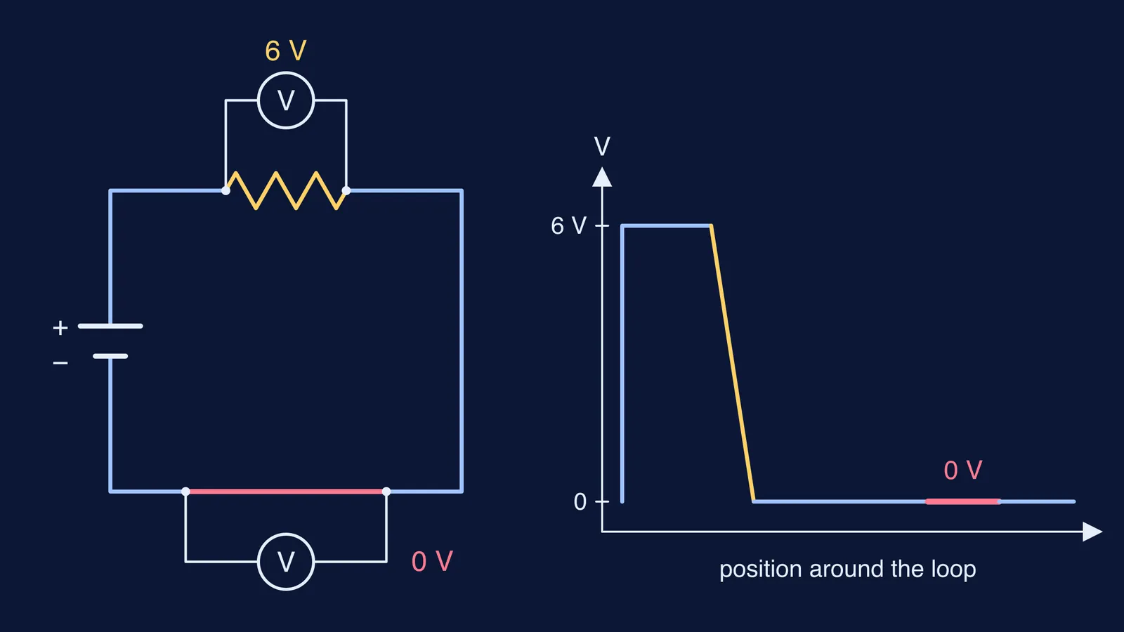
Think of the potential as height along the loop: the battery lifts it, each resistor drops it, and each ideal wire is level ground. A voltmeter measures a change in height, and on level ground there is none.
Worked example: one battery, one resistor, two voltmeters
Take an ideal 6 V cell connected to a single 3 Ω resistor with ideal wires. Connect voltmeter V1 across the resistor and voltmeter V2 across a length of the connecting wire.
Current: I = V/R = 6/3 = 2 A, and the same 2 A flows through the wire.
V1 across the resistor: V = IR = 2 × 3 = 6 V.
V2 across the wire: V = IR = 2 × 0 = 0 V.
Check with the loop rule: the cell gives +6 V, the resistor drops 6 V, the wire drops 0 V, and 6 − 6 − 0 = 0.
Now make it real. OpenStax lists copper's resistivity at 20 °C as 1.68 × 10⁻⁸ Ω·m, and works out that a 5 m length of 12-gauge copper wire (2.053 mm diameter) has a resistance of 0.025 Ω (OpenStax, Example 9.5). If that wire carried our 2 A, a voltmeter across it would read about 2 × 0.025 = 0.05 V, less than 1% of the 6 V across the resistor. That is why textbooks treat wires as ideal.
When does a voltmeter across a wire not read zero?
Check these before you write 0 V:
The wire has a stated resistance. If the question gives the wire a resistance, or asks about a long thin wire with a large current, use V = IR with that value.
There is a break in the path. If the stretch between the leads includes an open switch or a gap, no current flows and the voltmeter can read the full cell voltage; we work through that case in voltage across an open switch.
The leads span more than wire. If a resistor, cell or capacitor sits between the two points, you are measuring that component, not the wire.
The same idea explains the reverse trap. If an ideal wire is connected across a resistor, both ends of that resistor are at the same potential, so no current flows through it; see why no current flows through a short-circuited resistor.
How do you use this in JEE circuit problems?
Use the zero-drop rule as a first step:
Find every set of points joined only by ideal wire and give each set a single letter. Each letter is one potential.
Redraw the circuit with those sets merged into single points. Hidden parallel and short-circuit connections often appear here.
Choose one point as 0 V and write the potential at each letter by moving through cells and resistors.
Read each voltmeter as the difference between the letters its leads touch. Same letter means 0 V.
This node-labelling habit is the same one used to find the potential difference between two points in a circuit, and it turns most meter questions into subtraction.
Non-zero readings for meters across wires usually mean a method slip, not a formula gap. The Fermi Problem Library has worked problems with a step-by-step solver that explains the reasoning rather than printing an answer, so you can see where the redraw step changes the result.
Try the self-test on your next practice circuit: label the nodes first, then read the meters.