
On this page
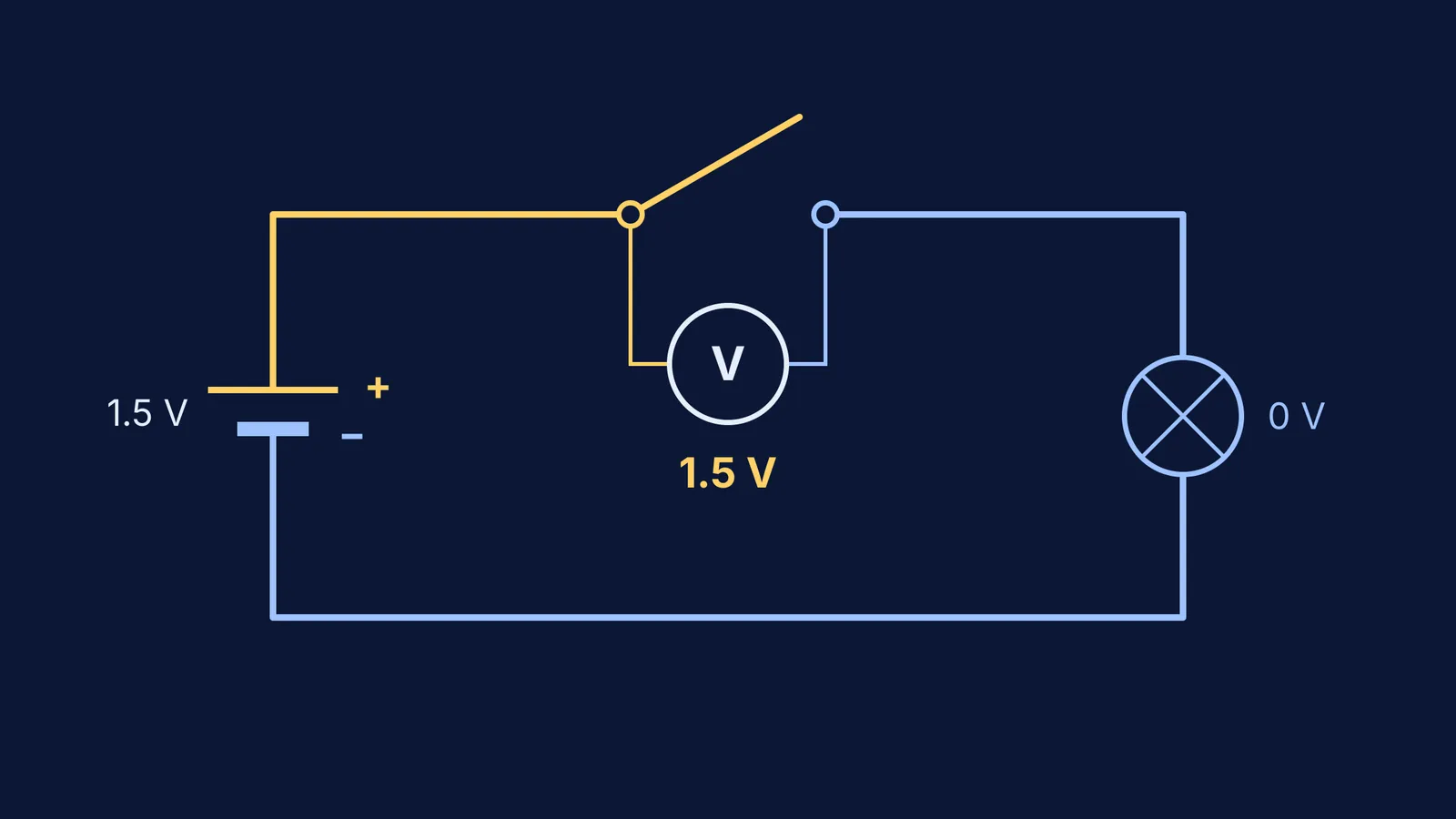
Picture the simplest circuit in your physics textbook: one cell, one bulb and one switch in a single loop. The switch is open, so the bulb is dark. You have a voltmeter. Before you read on, write down three numbers: the reading across the switch, across the bulb and across the cell.
Many students write 0 V for the switch, because "nothing is flowing there". In a questionnaire given to 145 high school students and 21 physics teachers, Cohen, Eylon and Ganiel found that current was the main concept students reasoned with, and that potential difference was seen as a consequence of current rather than its cause (American Journal of Physics, 1983). The open switch is where that idea breaks.
What does a voltmeter read across an open switch?
It reads the full voltage of the cell. The reasoning takes three steps, using textbook rules from OpenStax College Physics 2e.
With the switch open, no current flows anywhere in the loop.
With no current, the bulb has no voltage across it, because V = IR and I is zero.
Kirchhoff's loop rule says the algebraic sum of changes in potential around any closed loop must be zero. The cell raises the potential by its full voltage, the bulb and the wires drop nothing, so the whole drop must sit across the gap in the switch.
The voltmeter does not spoil this. A voltmeter is connected in parallel with whatever it measures and draws very little current when its resistance is much larger than the device's (OpenStax, DC voltmeters and ammeters). Our guide to connecting an ammeter and a voltmeter correctly shows where each meter goes.
The cell reads its full emf too. The emf is the potential difference of a source when no current is flowing (OpenStax, emf and terminal voltage).
Worked example: predict, then close the switch
Take a cell of emf 1.5 V with internal resistance 0.5 Ω, and a bulb of 5.0 Ω. A real filament's resistance rises as it heats, so treat 5.0 Ω as the hot value. The formulas are the loop rule and terminal voltage V = emf − Ir, both from OpenStax.
Switch open:
Across the switch: 1.5 V
Across the bulb: 0 V
Across the cell: 1.5 V, because I = 0 makes Ir = 0
Switch closed:
Current: I = 1.5 ÷ (5.0 + 0.5) = 1.5 ÷ 5.5 ≈ 0.273 A
Across the bulb: 0.273 × 5.0 ≈ 1.36 V
Across the cell: 1.5 − (0.273 × 0.5) ≈ 1.5 − 0.14 = 1.36 V
Across the switch: about 0 V, because closed contacts behave like a short piece of wire
Check the loop: 1.5 − 0.14 − 1.36 − 0 = 0. The cell's reading fell a little once current flowed, which is the internal resistance at work; our explainer on emf and internal resistance of cells goes further.
Why does the voltage jump from the switch to the bulb?
Voltage is a difference in potential between two points, not a measure of how much current passes. When the switch is open, the gap has a huge resistance and takes the entire drop. When it closes, the gap disappears and the bulb becomes the main resistance in the loop, so the drop moves there and the bulb lights.
The same logic explains a classic fault-finding trick. In a series string, a broken filament acts like an open switch, so a voltmeter across the dead bulb reads the full supply voltage while the good bulbs read zero. Our post on what happens when one bulb in series fuses works through that case.
One safety note: by the same reasoning, the open contacts of a household switch can have the full mains voltage across them. Practise with cells in the school lab, and leave mains wiring to a qualified electrician.
How do you practise predict-then-measure?
Lillian McDermott and Peter Shaffer, of the Physics Education Group at the University of Washington, described how investigating student understanding of electric circuits helped build a research base for curriculum development (American Journal of Physics, 1992). For your own revision, turn prediction into a habit:
Write your prediction for every meter reading, with one line of reason for each.
Measure, in the lab or in a circuit simulation.
If a reading surprises you, name the rule you skipped: no current, V = IR, or the loop rule.
Change one thing, such as adding a second cell or a second bulb, and predict again before measuring.
Without a lab bench at home, the Fermi Simulation Lab has interactive simulations for the ideas that are easier to see than to read. For the numericals that follow, the Fermi Problem Library has worked problems with a step-by-step solver that explains the reasoning rather than printing an answer.
Try it tonight: cover the worked example above, predict all seven values, then check.