
On this page
When Charles Wheatstone popularized the four-resistor bridge circuit in his 1843 Bakerian Lecture (Wheatstone 1843), crediting Samuel Hunter Christie's 1833 invention, its primary purpose was null measurement. When arm resistances satisfy the balance ratio R₁/R₂ = R₃/R₄, both intermediate nodes sit at equal electric potentials, and zero current crosses the central detector.
In practical sensors and competitive exams like JEE Advanced, resistance ratios often deviate from equality. When R₁/R₂ ≠ R₃/R₄, the bridge becomes unbalanced, and an active current flows through the galvanometer. Because the bridge arm links two intermediate nodes, the resistors are neither purely in series nor in parallel. To calculate the galvanometer current, you must return to first principles: the network rules formulated in 1845 by German physicist Gustav Kirchhoff (Kirchhoff 1845).
Why does current flow across an unbalanced bridge?
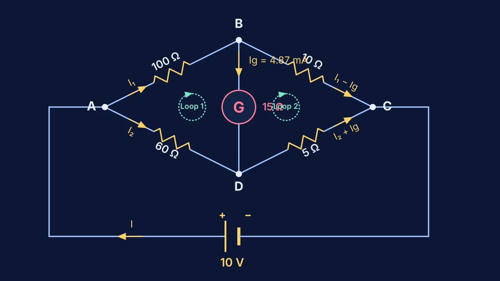
Consider four nodes labeled A, B, C, and D. A DC source connects across nodes A and C, while a galvanometer of resistance G bridges nodes B and D. Branches ABC and ADC act as two parallel voltage dividers across the supply voltage V.
If both branches divide the voltage equally, the potentials at nodes B and D are identical (V_B = V_D). No charge moves through the meter. When arm ratios differ, a potential difference (V_B − V_D ≠ 0) develops across the bridge. In sensitive instruments like Arsène d'Arsonval's moving-coil galvanometer, this potential difference drives an electric current that deflects the pointer, governed by the current and voltage sensitivity of a galvanometer.
How do you set up Kirchhoff loop equations for the bridge?
Finding the bridge current requires Gustav Kirchhoff's junction rule (conservation of charge) and loop rule (conservation of energy) (Kirchhoff 1845). Using junction current labels minimizes the number of variables:
Junction A: Battery current I divides into I₁ along branch AB (resistance R₁) and I₂ along branch AD (resistance R₃). Thus, I = I₁ + I₂.
Junction B: Current I₁ enters, current I_g diverts downward through the galvanometer BD (resistance G), leaving (I₁ − I_g) to flow along branch BC (resistance R₂).
Junction D: Current I₂ from arm AD merges with I_g from the galvanometer, so (I₂ + I_g) flows along branch DC (resistance R₄).
Junction C: Currents (I₁ − I_g) and (I₂ + I_g) recombine into I, conserving charge.
Applying Kirchhoff's loop rule (ΣΔV = 0) around closed circuits gives three independent equations:
Loop ABDA (clockwise): −I₁ R₁ − I_g G + I₂ R₃ = 0, which rearranges to I₁ R₁ + I_g G − I₂ R₃ = 0.
Loop BCDB (clockwise): −(I₁ − I_g) R₂ + (I₂ + I_g) R₄ + I_g G = 0, which rearranges to (I₁ − I_g) R₂ − (I₂ + I_g) R₄ − I_g G = 0.
Outer Loop ADCEA (clockwise with battery V): −I₂ R₃ − (I₂ + I_g) R₄ + V = 0, giving I₂ R₃ + (I₂ + I_g) R₄ = V.
What is the step-by-step numerical solution for the galvanometer current?
Consider the benchmark problem from Chapter 3 of the Class 12 Physics curriculum (NCERT 2024):
Arm AB: R₁ = 100 Ω
Arm BC: R₂ = 10 Ω
Arm AD: R₃ = 60 Ω
Arm DC: R₄ = 5 Ω
Galvanometer BD: G = 15 Ω
Power supply: V = 10 V
First, check the balance condition: R₁/R₂ = 100/10 = 10, while R₃/R₄ = 60/5 = 12. Because 10 ≠ 12, the bridge is unbalanced, and current flows through the 15 Ω galvanometer (NCERT 2024).
Substitute these values into our loop equations (NCERT 2024):
Loop ABDA: 100 I₁ + 15 I_g − 60 I₂ = 0. Dividing by 5 gives 20 I₁ + 3 I_g − 12 I₂ = 0 (Equation 1).
Loop BCDB: 10(I₁ − I_g) − 5(I₂ + I_g) − 15 I_g = 0. Expanding and dividing by 5 gives 2 I₁ − I₂ − 6 I_g = 0 (Equation 2).
Loop ADCEA: 60 I₂ + 5(I₂ + I_g) = 10. Simplifying gives 65 I₂ + 5 I_g = 10, or 13 I₂ + I_g = 2 (Equation 3).
Solve by expressing I₁ and I₂ in terms of I_g:
From Equation 2: I₂ = 2 I₁ − 6 I_g.
Substitute into Equation 1: 20 I₁ + 3 I_g − 12(2 I₁ − 6 I_g) = 0, yielding −4 I₁ + 75 I_g = 0, so I₁ = 18.75 I_g.
Calculate I₂: I₂ = 2(18.75 I_g) − 6 I_g = 31.5 I_g.
Substitute I₂ into Equation 3: 13(31.5 I_g) + I_g = 2, which gives 410.5 I_g = 2.
Solving yields I_g = 2 / 410.5 A = 4 / 821 A ≈ 0.00487 A, or 4.87 mA (NCERT 2024).
The positive sign confirms current flows from node B to node D. When multi-loop algebra feels overwhelming, applying a clear step-by-step physics problem-solving method keeps equations organized. The Fermi Problem Library provides worked problems with a step-by-step solver that explains the reasoning rather than printing an answer.
How can you verify your answer without re-doing loop equations?
You can verify this result in seconds using Thévenin's theorem. Temporarily disconnect the galvanometer arm BD to determine the open-circuit voltage difference across the 10 V source (NCERT 2024):
Node B potential: V_B = 10 V × (10 Ω / 110 Ω) = 10/11 V ≈ 0.9091 V.
Node D potential: V_D = 10 V × (5 Ω / 65 Ω) = 10/13 V ≈ 0.7692 V.
Open-circuit Thévenin voltage: V_th = V_B − V_D = 10/11 V − 10/13 V = 20/143 V ≈ 0.1399 V.
Short the 10 V battery to determine the Thévenin resistance R_th seen between terminals B and D:
R_th = (100 Ω || 10 Ω) + (60 Ω || 5 Ω) = (100/11) Ω + (60/13) Ω = 1960/143 Ω ≈ 13.7063 Ω.
Reconnecting the 15 Ω galvanometer gives: I_g = V_th / (R_th + G) = (20/143) / (1960/143 + 15) = 20 / 4105 A = 4 / 821 A ≈ 4.87 mA (NCERT 2024). The values match perfectly. The Fermi Simulation Lab offers interactive simulations for ideas that are easier to see than to read, showing how shifting arm resistances reverses meter current in real time.