
On this page
When an open switch connects two nodes in a capacitor circuit, those nodes sit at independent potentials. Closing the switch turns them into an equipotential conductor. Because charge flows from higher to lower potential until the electric field along the connecting wire vanishes, a transient surge traverses the switch.
Under the CBSE Senior Secondary Physics Curriculum, capacitors in series and parallel are core electrostatics topics. In steady-state DC circuits, fully charged capacitors block direct current. However, closing a switch redistributes charge across the plates. Rather than integrating transient current over time, you find the charge that crossed the switch by comparing the electrostatic equilibrium states before and after switching.
How do you calculate the charge flowing through a switch?
The most dependable approach is the island method, which applies nodal charge conservation. An "island" is a plate-and-wire cluster isolated from external sources when the switch is open.
Determine initial charges. With the switch open, find the voltage across each capacitor using standard reduction formulas, as described in OpenStax University Physics. Recall why capacitors in series carry equal charge. Using q = C × V with signed charges, sum the charges on all plates touching the switch terminal to find Q_initial.
Determine final charges. Redraw the circuit with the switch closed. Find the new junction potential using the node potential method for capacitor networks. Calculate the updated plate charges (q' = C × V') and sum them on the same plates to find Q_final.
Apply conservation. The charge Δq entering the node through the switch is:
Δq = Q_final − Q_initial. A positive value indicates charge entered the node; a negative value means charge left.
When solving multi-loop networks where voltages shift across several nodes, the Fermi Problem Library offers worked problems with a step-by-step solver that explains the reasoning rather than printing an answer.
How much charge flows across a switch in a capacitor bridge?
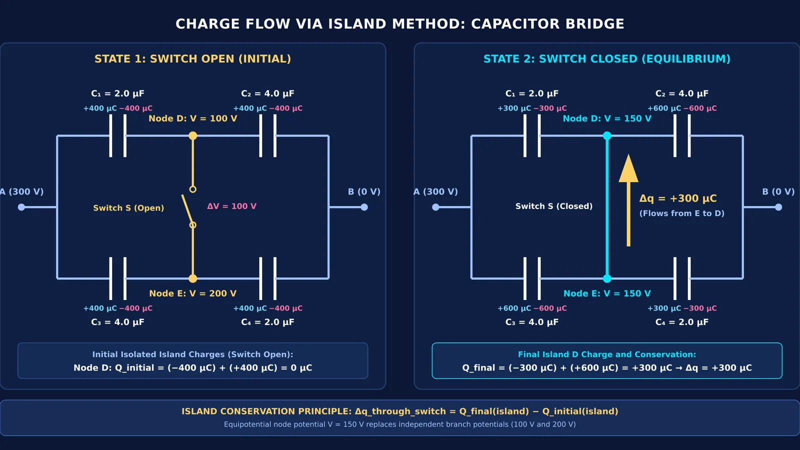
Extending the series-parallel network principles in the OpenStax Physics Problem Set, consider a classic bridge circuit. A 300 V potential difference connects terminal A (300 V) and terminal B (0 V):
Top branch: C₁ = 2.0 μF and C₂ = 4.0 μF in series, with junction D between them.
Bottom branch: C₃ = 4.0 μF and C₄ = 2.0 μF in series, with junction E between them.
Switch S connects junction D to junction E.
Before closing switch S, each branch has equivalent capacitance C_eq = (2.0 × 4.0) / (2.0 + 4.0) = 4/3 μF and carries Q = (4/3 μF) × 300 V = 400 μC. The potential at D is V_D = 300 V − (400 μC / 2.0 μF) = 100 V, while V_E = 300 V − (400 μC / 4.0 μF) = 200 V. The open switch holds a 100 V difference. Because junction D holds the negative plate of C₁ (−400 μC) and the positive plate of C₂ (+400 μC), its initial net charge is Q_D,initial = 0 μC.
Closing switch S unifies D and E into one equipotential node. The network becomes two parallel pairs in series: (C₁ ∥ C₃) with 6.0 μF in series with (C₂ ∥ C₄) with 6.0 μF. The 300 V drop divides equally, setting V_common = 150 V.
Final charges on plates meeting at D are:
Right plate of C₁: −q₁' = −2.0 μF × (300 V − 150 V) = −300 μC.
Left plate of C₂: +q₂' = +4.0 μF × (150 V − 0 V) = +600 μC.
The net final charge at node D is Q_D,final = −300 μC + 600 μC = +300 μC. By charge conservation: Δq = Q_D,final − Q_D,initial = +300 μC − 0 μC = +300 μC. Exactly 300 μC of positive charge flows through switch S from junction E to junction D.
Where does the dissipated energy go during charge redistribution?
Under the electrostatic energy formula U = 1/2 C V² from OpenStax University Physics, the initial stored electrostatic energy in this bridge was U_initial = 2 × (1/2)(4/3 μF)(300 V)² = 0.120 J. After switching, equivalent capacitance rose to 3.0 μF, storing U_final = (1/2)(3.0 μF)(300 V)² = 0.135 J. Because total charge drawn grew from 800 μC to 900 μC, the battery supplied an extra 100 μC, doing work W_battery = (100 μC) × (300 V) = 0.030 J. Stored energy increased by ΔU = 0.015 J, leaving H = W_battery − ΔU = 0.015 J (15 mJ) dissipated.
While standard textbooks treat this loss as wire resistance heating, research by Boykin et al. in the American Journal of Physics proves that even with zero resistance, accelerating charges radiate electromagnetic waves carrying away 100% of the dissipated energy.
To see how energy conservation and circuit laws connect across physics, the Fermi Concept Library covers every concept with its own lesson and its place in the concept map.
What mistakes do students make in switch problems?
Three common oversights lead to incorrect results:
Neglecting plate signs. Adding charge magnitudes rather than signed values corrupts the nodal sum, especially on capacitors with unequal plate charges.
Overlooking battery work. Switching alters equivalent capacitance, frequently causing the battery to deliver fresh charge.
Confusing node voltage with plate charge. Node voltage is only an intermediate value; you must calculate individual plate charges to determine Δq.
If an unfamiliar layout leaves you uncertain about which plates form an isolated island, Fermi's AI tutor can work out what you already know and build a plan for the session, drawing the figure and checking understanding as it goes.