

On this page
When you first study electricity and circuits, you learn a hard-and-fast rule: capacitors connected in series always carry the same charge. If you have a chain of three capacitors of different sizes and connect them to a battery, you might expect the larger ones to hold more charge. But they do not. Each one holds exactly the same amount of charge Q.
To see why, we have to follow the electrons as they move.
Why do capacitors in series have the same charge?
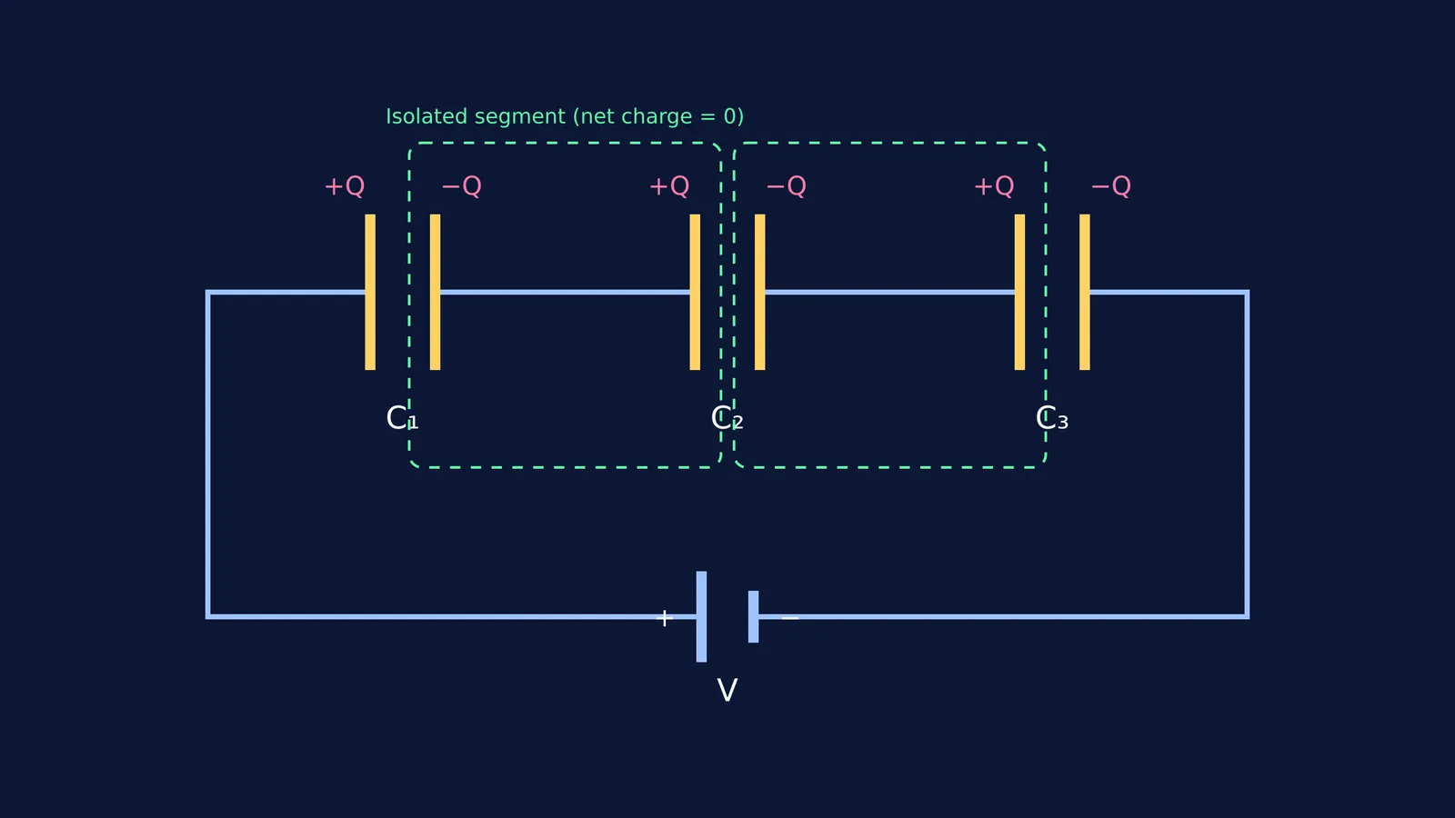
Imagine a circuit with three capacitors, C1, C2, and C3, connected end-to-end in a line, with a battery providing a voltage.
When the switch is closed, the positive terminal of the battery pulls electrons off the left plate of C1. This leaves the left plate of C1 with a positive charge of +Q. At the same time, the negative terminal of the battery pushes an equal number of electrons onto the right plate of C3, giving it a negative charge of −Q.
But what happens in the middle of the chain? The right plate of C1, the wire connecting them, and the left plate of C2 form an isolated metal segment. No electrons can jump across the gaps between the capacitor plates.
Before the battery was connected, this isolated segment was perfectly neutral. Because of the conservation of charge, its total net charge must remain zero. As the *University Physics Volume 2* textbook defines it, "When a charge Q in a series circuit is removed from a plate of the first capacitor (which we denote as −Q), it must be placed on a plate of the second capacitor (which we denote as +Q), and so on."
The +Q charge on the left plate of C1 strongly attracts the loose electrons in the nearby wire. Those electrons rush toward the right plate of C1 to get as close to the positive charge as possible. When they move, they leave behind a positive charge on the left plate of C2. So, the right plate of C1 becomes −Q, and the left plate of C2 becomes +Q. The total charge of that isolated segment is still (−Q) + (+Q) = 0.
This chain reaction ripples down the line. Every capacitor in the series ends up with +Q on one plate and −Q on the other. This is exactly why capacitors in series have the same charge, regardless of their individual capacitance values.
If this idea feels difficult to picture, you are not alone. Visualizing where the charges move is often the hardest part of electrostatics, which is where the Concept Library helps by mapping out the fundamental principles of electricity step by step.
How does voltage divide across capacitors in series?
While the charge Q is identical across all capacitors in series, the voltage across them is not.
The defining formula for a capacitor is C = Q/V, which can be rearranged as V = Q/C. Since Q is constant for every capacitor in the chain, the voltage drop V across any individual capacitor is inversely proportional to its capacitance C.
This means the smallest capacitor in a series circuit experiences the largest voltage drop. The battery's total voltage is divided among the capacitors, meaning V = V1 + V2 + V3.
How do you solve series capacitor problems?
When tackling exam problems, you can rely on a straightforward three-step framework.
Find the equivalent capacitance of the entire series chain.
Use the total battery voltage to calculate the common charge Q that flows from the battery.
Apply that same Q to each individual capacitor to find its specific voltage drop.
If you struggle with setting up these steps on a blank page, Fermi's AI tutor teaches rather than answers. It notices where you are stuck, checks your understanding as it goes, and decides whether to explain, ask, or show the next step.
A worked example
Suppose you connect a 3 μF capacitor and a 6 μF capacitor in series to a 9 V battery.
First, find the equivalent capacitance: 1/C = 1/3 + 1/6 1/C = 3/6 = 1/2 So, C = 2 μF.
Next, find the common charge drawn from the battery: Q = C × V Q = 2 μF × 9 V = 18 μC.
Finally, find the voltage drop across each capacitor. For the 3 μF capacitor: V1 = Q / C1 = 18 μC / 3 μF = 6 V.
For the 6 μF capacitor: V2 = Q / C2 = 18 μC / 6 μF = 3 V.
Notice how the total voltage (6 V + 3 V) equals the battery's 9 V, and the smaller 3 μF capacitor takes the larger share of the voltage. This inverse relationship between capacitance and voltage is a powerful tool to check your work during exams. If your calculation shows the largest voltage across the largest capacitor, you know immediately that something has gone wrong.
Understanding this distribution is crucial when analyzing Capacitors in DC circuits at steady state: charge and voltage. Once you master the basic rules of charge and voltage, you can confidently tackle more complex configurations, such as Capacitors and dielectrics: series, parallel and energy stored.


