
On this page
You flip the switch on a series circuit with DC supply V₀, resistor R, and inductor L. Ohm's law V = IR might suggest current leaps instantly to V₀/R. Instead, an ammeter shows zero current at switch closure, followed by a gradual rise.
That delay reflects electromagnetic inertia. Under Faraday's and Lenz's laws, changing current alters magnetic flux in the inductor coil, inducing an opposing back-EMF: ε = -L (dI/dt). At switch closure (t = 0⁺), this counter-voltage balances the supply voltage completely, holding current at zero. As shown in our guide to inductor behavior at t = 0 and t = ∞, the inductor acts initially as an open circuit before settling into a zero-resistance wire.
Why does current rise exponentially rather than linearly?
Kirchhoff's loop rule gives the circuit equation:
V₀ - L (dI/dt) - IR = 0
Rearranging clarifies the rate of change:
dI/dt = (V₀ - IR) / L
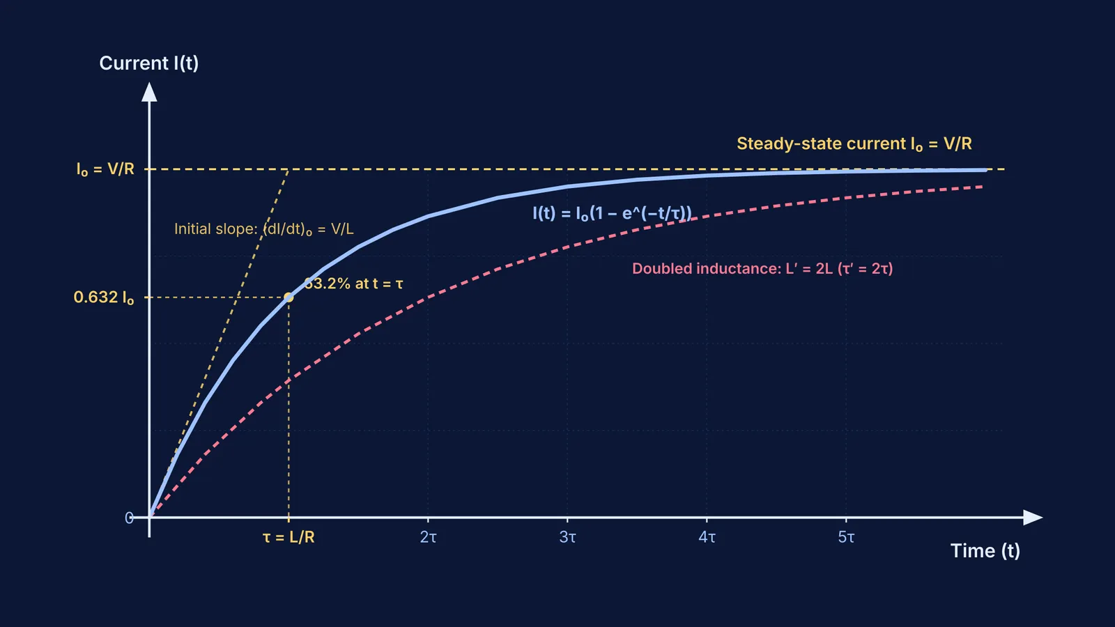
At switch closure (t = 0⁺), I = 0, so the resistor drop IR is zero and the inductor bears the full supply voltage, giving (dI/dt)₀ = V₀/L. As current builds, IR grows, leaving less voltage across the inductor and slowing dI/dt. Integrating from t = 0 yields the growth law:
I(t) = I₀ (1 - e^(-t/τ))
Here, I₀ = V₀/R is steady-state current and τ = L/R is the inductive time constant. As in charging and discharging in RC circuits, current approaches saturation asymptotically because growth rate stays proportional to the remaining gap (I₀ - I).
How do inductance and resistance determine the time constant?
The inductive time constant τ = L/R measures response speed in seconds (OpenStax University Physics Volume 2).
At t = τ:
I(τ) = I₀ (1 - e⁻¹) ≈ 0.6321 I₀
Current reaches 63.2% of maximum at t = τ, 86.5% at 2τ, 95.0% at 3τ, and 99.3% at 5τ, which marks steady state.
While increasing L delays growth by adding magnetic inertia, increasing R accelerates the approach. Because τ = L/R, doubling R halves the time constant. The final current ceiling I₀ = V₀/R is lower, but the circuit covers 63.2% of that smaller span in half the time.
Why test current growth in a simulation before solving numericals?
Physical inductors on a breadboard often mask transient dynamics behind winding resistance, switch bounce, and microsecond timescales.
In Physical Review Special Topics - Physics Education Research, Finkelstein et al. (2005) evaluated university physics students using interactive simulations against peers using physical lab benches. Simulation students achieved an average of 59% on final-exam circuit questions, compared to 48% for the physical-bench group. In a physical circuit challenge, simulation students finished faster (averaging 14.0 minutes versus 17.7 minutes) and explained circuit mechanisms more successfully (62% versus 55%).
A study by Zacharia (2007) tracking 88 undergraduates confirmed that combining simulations with physical labs generated higher conceptual gains than equipment alone. Furthermore, Moya (2018) showed that simulated transients teach circuit topology and time constants without consuming lecture hours.
In our analysis of testing circuit misconceptions with simulations, interactive visualization dispelled the myth that inductors permanently choke steady current. The Fermi Simulation Lab provides interactive simulations for the ideas that are easier to see than to read, letting you vary L, R, and voltage to inspect live curves.
A four-step predict-and-test framework for RL circuits
Before adjusting simulation sliders or calculating values, follow this four-step routine:
State initial and final limits: Set I(0⁺) = 0 and I(∞) = V₀/R to fix boundary states.
Calculate the time constant: Compute τ = L/R and locate the 63.2% current threshold.
Predict perturbation effects: Hypothesize whether doubling L or halving R broadens or compresses the rise before running the model.
Check voltage partition: Confirm that V_L(t) + V_R(t) = V₀ at all times, ensuring inductor voltage decays as resistor voltage climbs.
When practicing multi-loop circuits with inductors, the Fermi Problem Library offers worked problems with a step-by-step solver that explains the reasoning rather than printing an answer.
Worked example: calculating transient growth and energy
A DC source of V₀ = 12 V connects at t = 0 to an inductor of L = 30 mH (0.030 H) and a resistor of R = 15 Ω.
Maximum current: I₀ = V₀/R = 12 / 15 = 0.80 A.
Time constant: τ = L/R = 0.030 / 15 = 2.0 ms.
Initial growth rate: (dI/dt)₀ = V₀/L = 12 / 0.030 = 400 A/s.
Current at t = 2.0 ms (1τ): I(τ) = 0.80 × (1 - e⁻¹) = 0.506 A (63.2% of I₀).
Current at t = 6.0 ms (3τ): I(3τ) = 0.80 × (1 - e⁻³) = 0.760 A (95.0% of I₀).
Stored magnetic energy: U = (1/2) L I₀² = 0.5 × 0.030 × (0.80)² = 9.6 mJ.