

On this page
Why did early hip replacements fail?
In the 1940s and 1950s, surgeons rebuilt arthritic hips by copying natural anatomy. In 1946, French surgeons Jean and Robert Judet introduced acrylic femoral head replacements, as reported in *The Journal of Bone and Joint Surgery*, while George McKee developed metal-on-metal prostheses matching the 40 mm to 45 mm diameter of the natural femoral head. Within two to three years, nearly all loosened or tore from bone.
The failure lay in mechanics. Healthy cartilage bathed in synovial fluid yields a friction coefficient between 0.005 and 0.02, as detailed in John Charnley's 1960 joint lubrication study. When surgeons substituted synthetic acrylic or metal, the friction coefficient jumped ten to twenty times higher, reaching 0.1 to 0.4.
During single-leg stance, abductor muscles pull hard to level the pelvis, producing contact loads three to four times body weight. You can explore how contact angles govern sliding surfaces in our guide to the angle of friction and repose. Pressed against a 40 mm to 45 mm ball, this load created severe twisting torque that levered the cup out of the pelvis.
What is the low-friction principle in hip arthroplasty?
At Wrightington Hospital, John Charnley realised artificial joints operate in boundary contact under heavy, slow movement. The turning moment transmitted to the pelvic socket follows the torque equation:
τ = μ × W × r
where τ is frictional torque, μ is friction coefficient, W is joint contact load, and r is the ball radius.
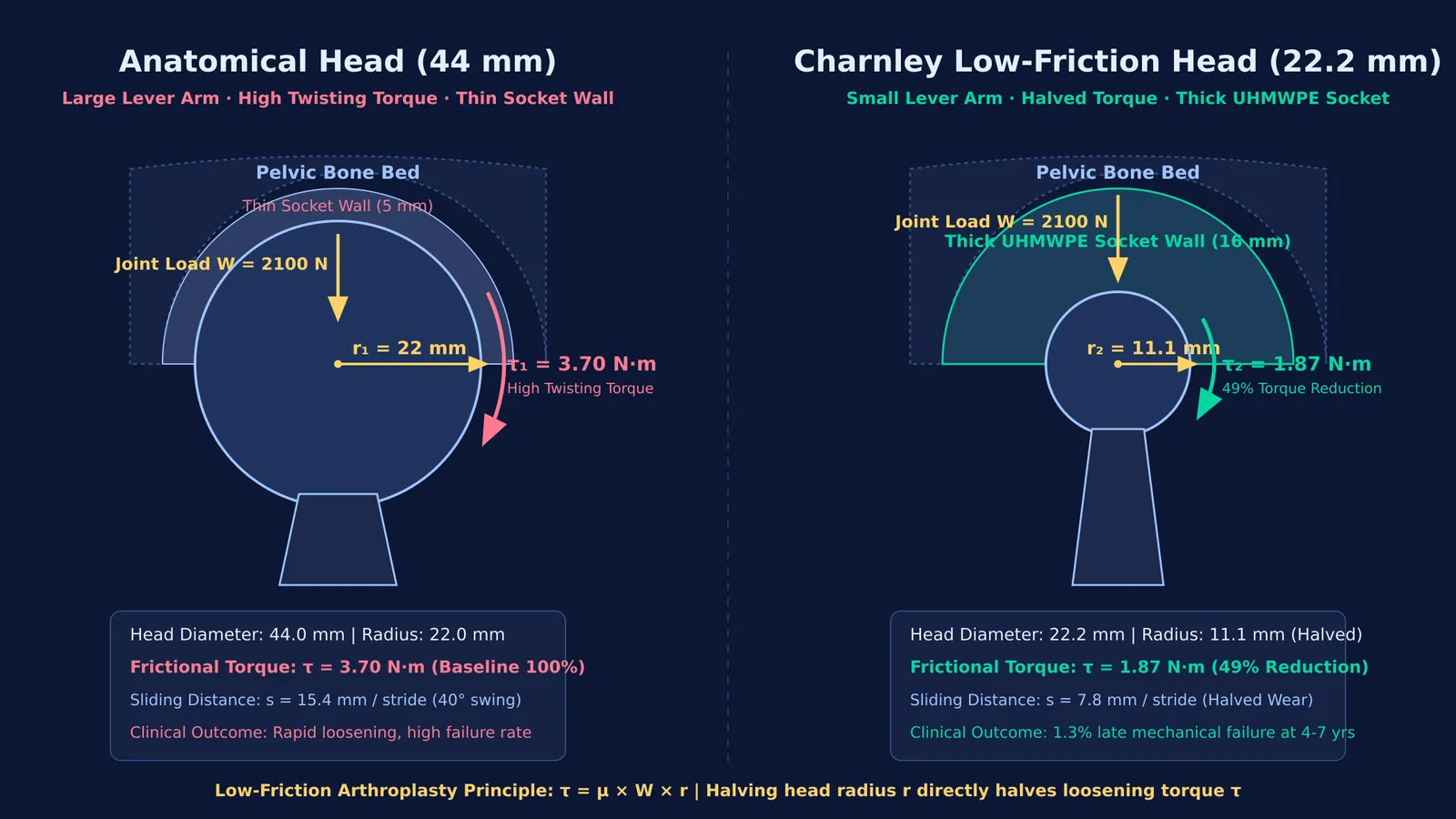
Because surgeons cannot alter friction laws or reduce patient weight, Charnley reduced the radius. In *The Lancet*92063-3), he introduced a femoral head diameter of 22.225 mm (7/8 inch), cutting the radius to 11.1 mm. Halving the radius compared to a 44 mm anatomical head cut pelvic twisting torque in half.
Shrinking the ball also halved wear. In a 40-degree (0.70-radian) stride, sliding distance is s = r × θ. Halving radius halves sliding distance. Under Archard's wear relation, this halved the volume of particulate debris generated per gait cycle.
When exploring how rotational torque and friction interact in physical systems, the Fermi Simulation Lab offers interactive simulations for ideas that are easier to see than to read.
How did PTFE fail and polyethylene succeed?
Charnley first chose polytetrafluoroethylene (PTFE or Teflon) because its static friction coefficient (~0.04) was the lowest of synthetic solids, as reported in *The Lancet*92063-3).
In the body, Teflon failed catastrophically. Cyclic body weight caused rapid wear and cold-flow creep. Shed Teflon particles triggered a fierce macrophage reaction, releasing enzymes that dissolved surrounding bone in periprosthetic osteolysis. In his 1963 report on tissue reactions to PTFE90759-1), Charnley documented the failures that forced him to re-operate on nearly 300 patients to remove destroyed cups.
In 1962, a supplier brought ultra-high-molecular-weight polyethylene (UHMWPE, Ruhrchemie RCH 1000). On Harry Craven's test rig, Teflon wore away in days, but UHMWPE ran for three weeks with zero measurable wear.
After testing a specimen in his own thigh to verify tissue tolerance, Charnley implanted the first clinical UHMWPE socket in November 1962. Similar biomaterial advances transformed medicine, as seen in how Otto Wichterle developed the soft contact lens. In *The Journal of Bone and Joint Surgery*, Charnley documented 379 primary operations followed for four to seven years: cemented sockets showed late mechanical failure in only 1.3% of 210 cases.
How does acrylic cement secure the implant in living bone?
The third pillar was fixation. In 1960, Charnley published his technique of anchoring femoral stems with self-curing poly(methyl methacrylate) (PMMA) acrylic cement in *The Journal of Bone and Joint Surgery*.
PMMA acts as a mechanical grout rather than a glue. Mixed into a dough, it penetrates cancellous bone pores before hardening, creating an interlocking matrix that distributes joint loads across a broad area to prevent stress peaks.
To protect implants from bacteria, Charnley introduced laminar-airflow clean rooms and whole-body exhaust suits. In *Clinical Orthopaedics and Related Research*, he showed these measures cut deep infection rates from 8.9% down to 0.5%. Decades later, similar systems engineering enabled breakthroughs like the multichannel cochlear implant by Graeme Clark.
How do torque and wear compare across head sizes?
To quantify why Charnley chose a 22.2 mm ball over an anatomical 44 mm ball in his *Lancet* design92063-3), consider a 70 kg person (weight mg ≈ 700 N) in single-leg stance:
Contact load: Abductor muscle pull yields joint load W ≈ 3 × 700 N = 2100 N.
Friction: For steel on UHMWPE with fluid lubrication, μ ≈ 0.08.
Anatomical torque (r = 0.022 m): τ₁ = 0.08 × 2100 N × 0.022 m = 3.70 N·m.
Charnley torque (r = 0.0111 m): τ₂ = 0.08 × 2100 N × 0.0111 m = 1.87 N·m.
Sliding distance per stride (θ = 0.70 rad): s₁ = 0.022 m × 0.70 rad = 15.4 mm vs s₂ = 0.0111 m × 0.70 rad = 7.8 mm.
The 22.2 mm head cuts twisting torque from 3.70 N·m to 1.87 N·m (a 49% drop) and halves sliding distance, substantially reducing annual wear debris.
Students tackling mechanics and rotational statics can work through similar calculations on the Fermi Problem Library, which provides worked problems with a step-by-step solver that explains the reasoning rather than printing an answer.


