

On this page
A radio wave makes current in an antenna swing back and forth millions of times a second. Push it into an ordinary meter and the needle does not move: the pushes in each direction cancel out. In 1904 John Ambrose Fleming found a way to let the current through in one direction only. His valve, a vacuum diode, opened the way to electronics. This post covers how he found it, how it works, a worked rectifier example and what students can learn from him.
Who was John Ambrose Fleming?
Fleming was born in Lancaster, England, on 29 November 1849, according to his biography on the Engineering and Technology History Wiki. He studied at University College London, went on to Cambridge where he heard James Clerk Maxwell lecture, and consulted for the Edison Electric Light Company on incandescent lamps. In 1885 he joined University College London, where he spent the rest of his career. He was elected a Fellow of the Royal Society in 1892, knighted in 1929, and died on 18 April 1945, aged 95.
Where did the idea come from?
The IEEE milestone for the Fleming valve explains the starting point. In 1883 Thomas Edison had noticed that an extra electrode sealed into a light bulb could carry a current when it was positive compared with the hot filament. This "Edison effect" is now understood as electrons flowing from the hot filament to the electrode. Fleming studied it in the 1880s and presented a paper on it to the Royal Society in December 1889.
In 1899 Fleming became a scientific adviser to the Marconi company. Wireless needed a reliable detector. In his 1905 Royal Society paper, On the conversion of electric oscillations into continuous currents by means of a vacuum valve, he explains the problem: a high-frequency current "cannot directly affect an ordinary movable coil or movable needle galvanometer". What he needed was "a medium with perfect unilateral conductivity", a one-way path. He then remembered his old light-bulb observation and found that the one-way conduction still worked at high frequency.
He applied for a patent, GB 190424850, on 16 November 1904, for "Improvements in Instruments for Detecting and Measuring Alternating Electric Currents".
How does the valve let current flow one way?
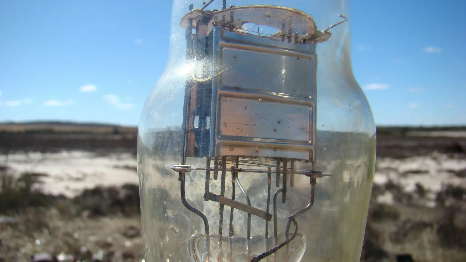
A heated filament gives off electrons. If the metal plate is positive, it attracts them and current flows. If the plate is negative, it repels them, and the cold plate gives off no electrons of its own, so no current flows backwards. NCERT's Class 12 chapter on semiconductor electronics describes this: in vacuum tubes electrons flow only from cathode to anode, "therefore, such devices are generally referred to as valves".
Fleming's paper is honest about his results. With his bulb, he reported, 80 to 90 per cent of the current through the vacuum was one-way. He argued that keeping the metal anode quite cool would make the rectification complete, and wrote that "an ideal and perfect rectifier for electric oscillations may, therefore, be found by enclosing a hot carbon filament and a perfectly cold metal anode in a very perfect vacuum".
Worked example: what does a meter read after rectification?
Take a sine-wave voltage with a peak of Vm = 10 V. This is a sample value.
Before rectification: over a full cycle the positive and negative halves cancel, so the average is 0 V. A moving-coil meter shows nothing.
After a half-wave rectifier: only the positive halves pass. The average over a full cycle is Vm/π = 10 / 3.1416 ≈ 3.18 V.
After a full-wave rectifier: both halves are made positive, so the average doubles to 2Vm/π ≈ 6.37 V.
Frequency: a half-wave rectifier's output repeats once per input cycle, so a 50 Hz input gives a 50 Hz output. Full-wave output repeats twice per cycle, 100 Hz.
Common mistakes to avoid:
Using Vm/2 for the average. A sine wave is not a triangle. The half-wave average is Vm/π, about 0.318 Vm.
Mixing average and rms. The rms value of the full sine wave, Vm/√2 ≈ 7.07 V, is a different quantity.
Forgetting the blocked half. The average is taken over the whole cycle, including the half where nothing flows.
Our guide to half-wave and full-wave rectifiers has more practice with the semiconductor diodes that replaced Fleming's valve.
What happened next?
The IEEE milestone notes that the valve could detect Morse code messages straight away, but mattered more as the ancestor of a new tube. After reading Fleming's 1905 paper, Lee de Forest added a third electrode and made the triode, which could amplify. That story is in our post on Lee de Forest and the triode.
What can a student take from how Fleming worked?
Keep old observations. The key fact came from his own experiments fifteen years earlier.
State the need exactly. "A medium with perfect unilateral conductivity" told him what to look for.
Report imperfect results. He gave the 80 to 90 per cent figure and explained what would improve it.
If a rectifier question goes wrong and you cannot see why, the Fermi Problem Library has a step-by-step solver that explains the reasoning, so you can find the step where your method slipped.
Next step: repeat the worked example for a peak of 15 V and check that the half-wave average is about 4.77 V.