

On this page
A single radio dish, however large, sees the sky in a blur, because radio waves are so long. The Giant Metrewave Radio Telescope (GMRT) gets round this by spreading 30 dishes across the countryside north of Pune and combining their signals. This post covers Govind Swarup, the radio astronomer behind it, how the telescope works, and three short calculations that use the wave optics and modern physics in your syllabus.
Who was Govind Swarup?
The Royal Society's biographical memoir of Govind Swarup gives his dates as 23 March 1929 to 7 September 2020. He studied at the University of Allahabad, joined the National Physical Laboratory in New Delhi, and went to Australia on a fellowship to work in radio astronomy under J. L. Pawsey. He then completed a PhD with Ronald Bracewell at Stanford, before accepting Homi Bhabha's offer to start radio astronomy at the Tata Institute of Fundamental Research (TIFR).
At TIFR he conceived and built the Ooty Radio Telescope, a novel, low-cost, equatorially mounted cylindrical telescope. In the late 1980s he conceived and led the construction of the GMRT, which the memoir says was again based on a pioneering design.
What is the GMRT?
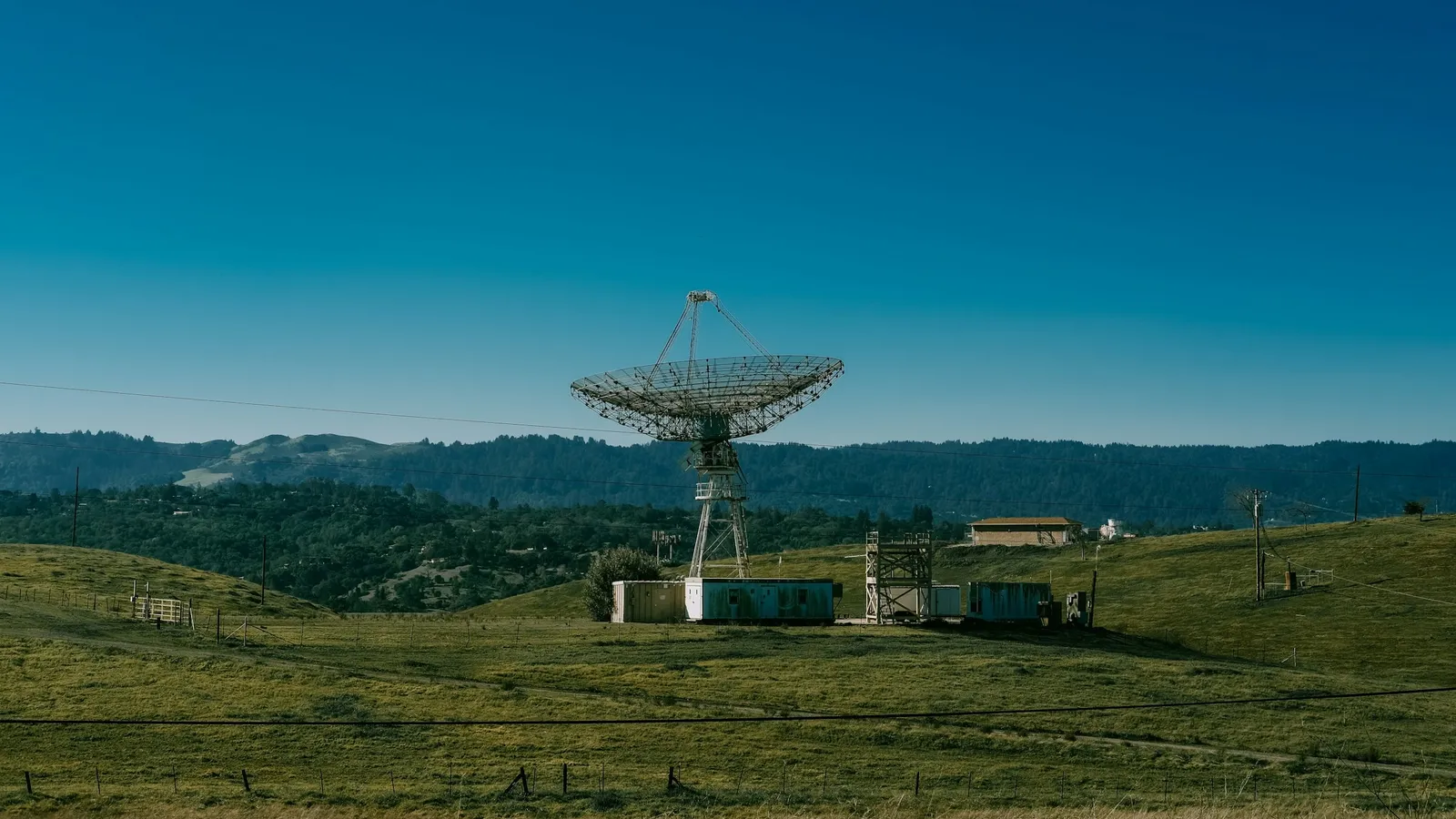
According to the National Centre for Radio Astrophysics (NCRA-TIFR), the GMRT is about 80 km north of Pune, near Narayangaon. It has 30 fully steerable parabolic dishes, each 45 m across, spread over distances of up to 25 km. Fourteen sit in a compact central array of about 1 square km, and the other sixteen lie along three arms of a rough "Y". It observes in bands centred near 50, 153, 233, 325, 610 and 1,420 MHz.
Why metre wavelengths? NCRA says man-made radio interference is considerably lower in this part of the spectrum in India, and that no large facility elsewhere had been built to exploit it.
The dishes use what NCRA calls the SMART design, for Stretch Mesh Attached to Rope Trusses. Instead of a heavy solid surface, thin stainless steel wire ropes are stretched between 16 parabolic frames, and a mesh of 0.55 mm wire is laid over them, with holes from 10 mm by 10 mm at the centre to 20 mm by 20 mm at the edge. That is how 30 large dishes were built at relatively small cost.
Worked example 1: why 30 dishes make 435 telescopes
Each pair of dishes acts as an interferometer. The number of pairs from 30 dishes is
30 × 29 ÷ 2 = 435.
NCRA gives the same figure: correlating signals from all 435 possible pairs over several hours lets astronomers build an image as sharp as one from a single dish 25 km across.
Worked example 2: how sharp is the image?
The smallest angle a telescope can resolve is roughly θ ≈ λ/D, with θ in radians. Convert to arcseconds by multiplying by 206,265.
At 1,420 MHz: λ = c/f = 3.0 × 10⁸ ÷ 1.42 × 10⁹ = 0.211 m. With D = 25,000 m, θ = 0.211 ÷ 25,000 = 8.45 × 10⁻⁶ rad = 1.7 arcseconds.
At 610 MHz: λ = 0.492 m, so θ = 1.97 × 10⁻⁵ rad = 4.1 arcseconds.
One 45 m dish at 1,420 MHz: θ = 0.211 ÷ 45 = 4.7 × 10⁻³ rad, about 970 arcseconds or 16 arcminutes.
NCRA quotes a best resolution of about 2 arcseconds at 1.4 GHz, rising to about 60 arcseconds at the lowest frequencies, which matches. The array is roughly 550 times sharper than any one of its dishes.
The mesh holes, at 10 to 20 mm, are far smaller than wavelengths of 0.2 m to 6 m, which is why a mesh can stand in for a solid reflector at these frequencies.
Worked example 3: finding young galaxies with a 21 cm line
NCRA lists among the GMRT's main goals the search for neutral hydrogen in the early universe, through hydrogen's radio line at 1,420 MHz. Expansion of the universe stretches that wave, so the observed frequency is f = 1,420 MHz ÷ (1 + z), where z is the redshift.
z = 3: f = 1,420 ÷ 4 = 355 MHz.
z = 10: f = 1,420 ÷ 11 = 129 MHz.
NCRA says this line should appear between about 350 and 130 MHz for clouds at redshifts 3 to 10, exactly the metre-wave range the GMRT was built for. Its other headline goal is the study of pulsars, rapidly rotating neutron stars, which our post on Jocelyn Bell Burnell and pulsars introduces.
What mistakes do students make with these calculations?
Using one dish's diameter for the array. For the combined image, D is the longest baseline.
Forgetting to convert MHz. 1,420 MHz is 1.42 × 10⁹ Hz.
Dividing by z instead of 1 + z. At z = 3 the frequency falls to a quarter, not a third.
Leaving θ in radians when comparing with arcseconds. Multiply by 206,265.
For a refresher on where radio waves sit among other radiation, see our guide to the electromagnetic spectrum.
What can a student take from Swarup's way of working?
Twice, the memoir shows, Swarup built a world-class telescope by rethinking the design rather than copying an expensive one: first the cylindrical Ooty telescope, then the GMRT's light mesh dishes. He matched the instrument to India's advantages, a quiet radio band and the space to spread dishes out.
That habit transfers to problem solving: before reaching for a heavy method, ask what the problem actually needs. If interference and diffraction still feel abstract, the Fermi Simulation Lab has interactive simulations for ideas easier to see than read, so you can watch how slit spacing changes a pattern.
Calculate the resolution of the GMRT at 325 MHz, then check it lies between NCRA's two quoted limits.