
On this page
Semiconductor devices look like a scoring chapter: a few definitions, one graph, some circuits. Then marks leak away. A diode gets treated as a perfect switch, a cell is read the wrong way round, or "majority" becomes "minority". Here are the three mistakes, a worked circuit, and a checklist for your next mock test.
When can you treat a diode as ideal?
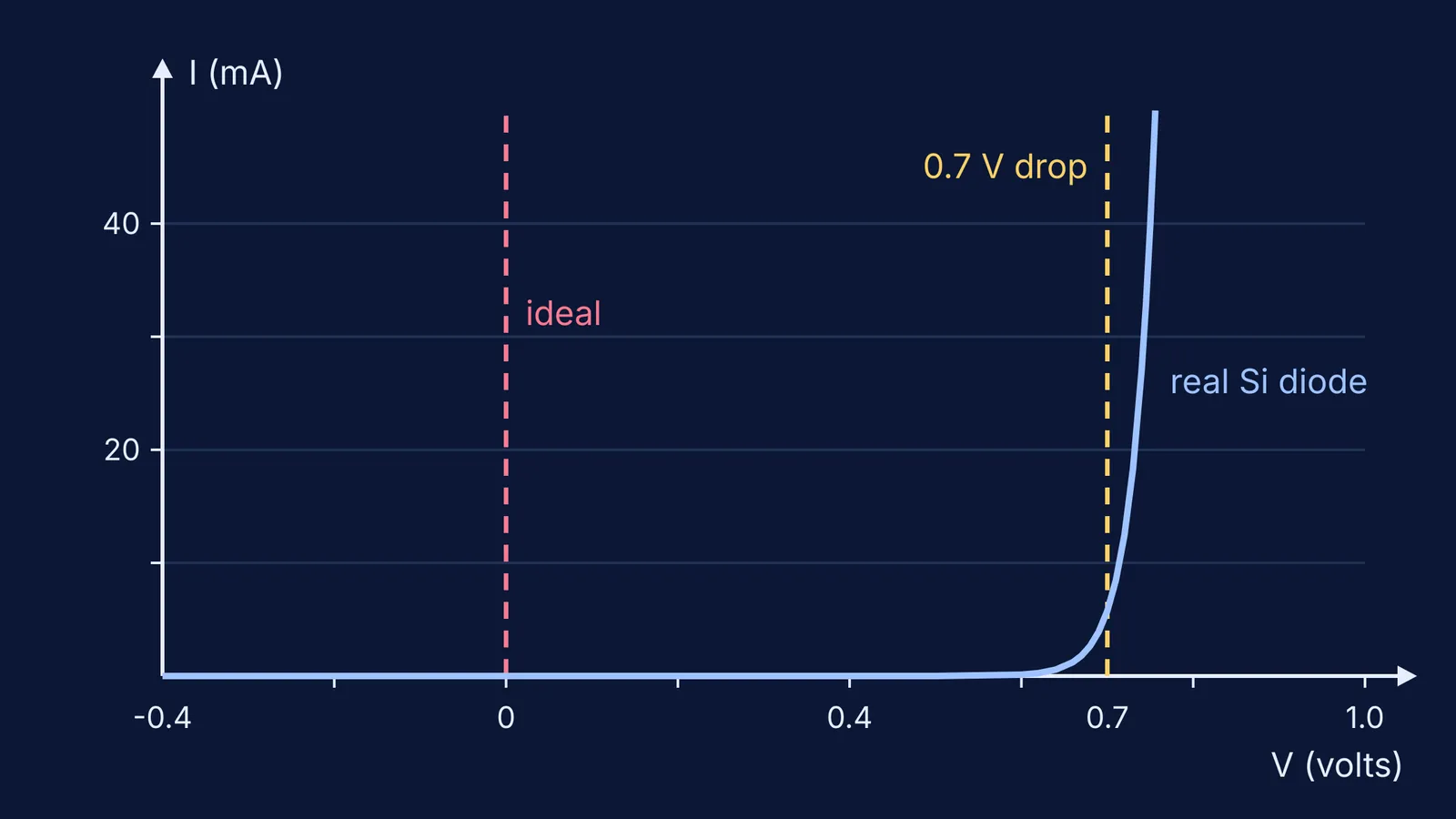
An ideal diode is a switch: zero resistance one way, infinite resistance the other, no voltage lost. A real silicon diode is different. The NCERT Class 12 Physics chapter on semiconductor electronics says the current stays almost negligible until the forward voltage crosses the threshold, or cut-in, voltage of about 0.7 V for silicon and about 0.2 V for germanium (NCERT, section 14.6). After that the current rises steeply, which is why a constant 0.7 V drop is a good model for most exam circuits.
Here is the test. Compare the source voltage with the drop.
A 12 V cell, a 1 kΩ resistor and a forward-biased silicon diode. Ideal: 12/1000 = 12 mA. With the drop: (12 − 0.7)/1000 = 11.3 mA. About 6% apart; the ideal answer is close.
A 1.2 V cell, a 100 Ω resistor and the same diode. Ideal: 1.2/100 = 12 mA. With the drop: (1.2 − 0.7)/100 = 5 mA. The ideal answer is more than double the real one.
How do you tell forward bias from reverse bias?
A diode is forward biased when the p-side is connected to the positive terminal and the n-side to the negative terminal; reverse the connection and it is reverse biased (NCERT, sections 14.6.1 and 14.6.2). In the symbol, the triangle is the p-side and the bar is the n-side, and the arrow points in the direction of conventional current under forward bias.
The common slip is to look at which end of the cell is "near" the diode. Do this instead:
Take the diode out and mark the potential of the node at the triangle and the node at the bar.
If triangle > bar by more than the cut-in voltage, the diode is on.
If not, it is off and carries only a tiny reverse current, which NCERT says can be taken as zero for practical purposes.
With two or more diodes, assume a state for each, solve, then check that every "on" diode carries current along its arrow and every "off" diode has less than the cut-in voltage across it in the forward direction. If a check fails, flip that assumption and solve again. Our guide to diode circuit analysis for JEE has more practice.
The check matters. In an exploratory study that interviewed third-year electrical engineering students as they solved diode problems aloud, Adam, Harlow, Lord and Kautz (2017) found that half did not use what they already knew, including I-V curves, to check their answers.
If your answers keep going wrong and you cannot see why, the Fermi Problem Library has worked problems with a step-by-step solver that explains the reasoning, so you can find the step where the bias went wrong.
Which carriers are majority and which are minority?
In an n-type semiconductor, electrons are the majority carriers and holes the minority carriers; in a p-type semiconductor, holes are the majority carriers and electrons the minority (NCERT, section 14.4). That part most students get right. The marks go in what comes next.
Reverse current is a minority-carrier current. NCERT says it is limited by the concentration of minority carriers on either side of the junction, not by the applied voltage, which is why it stays almost flat until breakdown.
Forward bias injects minority carriers. Electrons from the n-side enter the p-side, where they are minority carriers, and holes go the other way. NCERT calls this minority carrier injection.
Doping does not charge the crystal. An n-type crystal stays neutral, because each extra electron is balanced by a fixed positive donor ion.
To practise the numbers, our post on carrier concentration in n-type and p-type semiconductors uses the n_e n_h = n_i² relation from the same chapter. To rebuild the idea from the start, the Fermi Concept Library has a lesson for each concept and shows its place in the map.
A checklist for your next mock test
Did the question say "ideal"? If not, did you subtract 0.7 V (silicon) or 0.2 V (germanium)?
Did you mark the potential at the triangle and at the bar before deciding on or off?
In multi-diode circuits, did you check every assumed state after solving?
In theory answers, did you say reverse current comes from minority carriers and forward bias injects them?
Before you move on from your next diode question, sketch its I-V curve and check that your answer sits on it.