

On this page
Where is the image formed by a diverging lens?
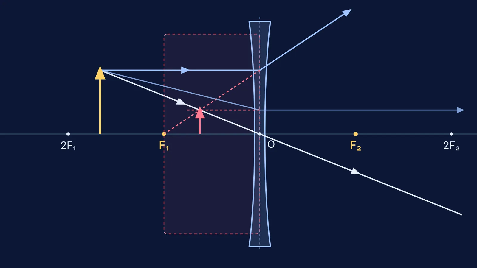
When light from a real luminous or illuminated object strikes a diverging (concave) lens, the lens bends the transmitted rays outward, away from its principal axis. Because the refracted rays fan apart, they never physically intersect on the transmission side of the glass. Instead, an observer looking through the lens sees those diverging rays as though they originate from a virtual point situated on the object's side.
According to Table 9.5 of NCERT Class 10 Science, the image of any real object in front of a concave lens is always formed between the optical centre (O) and the principal focus (F₁). Regardless of whether you place the object hundreds of metres away, beyond twice the focal length (2F₁), or right next to the glass inside the focal length, the resulting image is always virtual, erect, and diminished. Unlike a converging (convex) lens, which cycles through five distinct real image regimes before forming a magnified virtual image, a single diverging lens has only one geometric state for real objects: a miniature upright reproduction trapped strictly within the focal boundary.
Understanding this property prevents common exam mistakes. Students often confuse virtual images with invisible ones, but a virtual image is directly visible to the human eye or a camera, because the eye's crystalline lens converges the diverging wavefronts onto the retina.
How do ray diagrams locate the virtual image?
To find where the image forms geometrically, standard optics traces two or three principal rays from the highest point of an object of height h placed at distance u from the lens, as formalised in OpenStax University Physics:
The parallel ray: A ray travelling parallel to the principal axis refracts through the concave lens and diverges outward along a trajectory whose straight-line backward extension passes directly through the primary focus F₁ on the incident side.
The central ray: A ray passing directly through the optical centre O continues without any angular deviation, following a straight path across both interfaces under the thin-lens approximation.
The focal ray: A ray directed toward the secondary focal point F₂ on the opposite side of the lens refracts at the lens plane to emerge parallel to the principal axis, projecting backward as a horizontal line.
Because the central ray travels from the object tip downward toward the optical centre (O), and the back-projected parallel ray slopes from the lens down toward F₁, the two lines must intersect in the triangular wedge formed by the lens plane, the principal axis, and the focal point. This geometric intersection is forced to lie at a horizontal distance from the lens that is strictly shorter than both the object distance and the focal length. Connecting this intersection perpendicularly to the principal axis gives an upright virtual arrow of height h' that is visibly smaller than the original object.
For students reviewing lens behaviour across board exams, understanding this geometric proof connects directly to broader optics principles, including light in Class 10 and the lens formula and ray optics sign conventions.
Why does the lens formula constrain the image between F and the lens?
The geometric result is backed by the thin-lens formula derived from refraction across curved surfaces, as detailed in NCERT Class 12 Physics:
1/v − 1/u = 1/f
Under the New Cartesian sign convention, distances measured against the direction of incident light are negative:
For a real object placed to the left of the lens at a positive distance x, the object coordinate is u = −x (where x > 0).
For a diverging lens, the focal length is negative, so f = −F_len (where F_len > 0).
Substituting these values into the lens formula yields:
1/v − 1/(−x) = 1/(−F_len)
1/v + 1/x = −1/F_len
1/v = −(1/F_len + 1/x) = −(x + F_len) / (x × F_len)
Inverting this expression solves for the image position:
v = −(x × F_len) / (x + F_len)
Two algebraic conclusions follow immediately from this exact solution:
Sign: Because x > 0 and F_len > 0, the numerator and denominator are both strictly positive, making v negative for every real object distance. A negative v means the image always forms on the incident side, verifying it is virtual.
Magnitude: The magnitude of the image distance is |v| = F_len × [x / (x + F_len)]. Because the ratio x / (x + F_len) is strictly less than 1 for any finite positive x, the image distance |v| is always strictly less than F_len.
Simultaneously, the linear magnification formula confirms the image orientation and scale:
m = v / u = [−(x × F_len) / (x + F_len)] / (−x) = F_len / (x + F_len)
Since F_len and (x + F_len) are both positive, m is strictly positive (erect image). Furthermore, since F_len < x + F_len, m is strictly less than 1 (diminished image).
When navigating multi-lens optical setups or sign-convention traps, the Fermi Problem Library provides worked problems with a step-by-step solver that explains the reasoning rather than printing an answer. If you are reviewing the foundational definitions, the Fermi Concept Library holds every concept in physics, chemistry, biology, mathematics and computing, each with its own lesson and its place in the map.
What happens to image size and position as the object moves?
Tracking the boundary limits reveals how the virtual image shifts across the full range of object positions:
Object at infinity (x → ∞): The term x / (x + F_len) approaches 1. The image distance |v| approaches the focal length F_len, and magnification m approaches 0. Parallel incident rays diverge as if emanating from a point-sized virtual focus at F₁.
Object between infinity and F (x > F_len): The image forms between F_len/2 and F_len. For instance, if an object is at x = 2F_len, the image forms at |v| = 2/3 F_len with magnification m = 1/3.
Object at the principal focus (x = F_len): Placing the object at F₁ yields |v| = F_len/2 and m = 1/2. The image lies exactly halfway between the focal point and the optical centre.
Object inside the focus (0 < x < F_len): As the object moves closer to the lens surface, the image distance shrinks toward 0, and magnification increases toward 1. The image remains upright and diminished, growing slightly closer to unit size without ever exceeding the object's height.
Worked numerical example
Consider an object of height h = 6.0 cm placed at distance u = −30 cm in front of a concave lens with focal length f = −20 cm.
Apply the lens formula: 1/v = 1/f + 1/u = 1/(−20 cm) + 1/(−30 cm) = −(3 + 2)/60 cm = −5/60 cm = −1/12 cm.
Calculate image distance: v = −12 cm. The negative sign denotes a virtual image formed 12 cm in front of the lens. Notice that 12 cm is strictly less than the 20 cm focal length, confirming the image lies between F₁ and O.
Compute magnification and image height: m = v / u = (−12 cm) / (−30 cm) = +0.40. Then h' = m × h = 0.40 × 6.0 cm = +2.4 cm. The positive sign indicates an erect image, and 2.4 cm confirms it is diminished.
A four-step diagnostic checklist
When solving concave lens numericals in board or entrance exams, verify your answer against these four checks:
Sign verification: Ensure both u and f are assigned negative signs before calculating.
Virtual confirmation: The calculated v must be negative. A positive v indicates an arithmetic error in transposing terms.
Boundary constraint: The magnitude |v| must be strictly less than the focal length |f|. If your answer gives |v| > |f|, recheck your algebraic fractions.
Magnification bounds: The magnification m must satisfy 0 < m < 1. Any result where m is negative or greater than 1 violates the physics of a single diverging lens.
These rules also govern combinations where a diverging lens serves as an eyepiece or corrective element, as explored in our guide to the lens maker's formula and lens combinations. For learners needing to picture how diverging rays bend away from the principal axis in real time, the Fermi Simulation Lab offers interactive simulations for the ideas that are easier to see than to read.


