On this page
A potential divider (or voltage divider) is a simple circuit that splits an input voltage into a smaller output voltage. While dividing voltage with two fixed resistors is useful, the circuit becomes a smart sensor when you replace one of those resistors with a component that reacts to its environment—like a Light Dependent Resistor (LDR) or a thermistor.
What does a potential divider do?
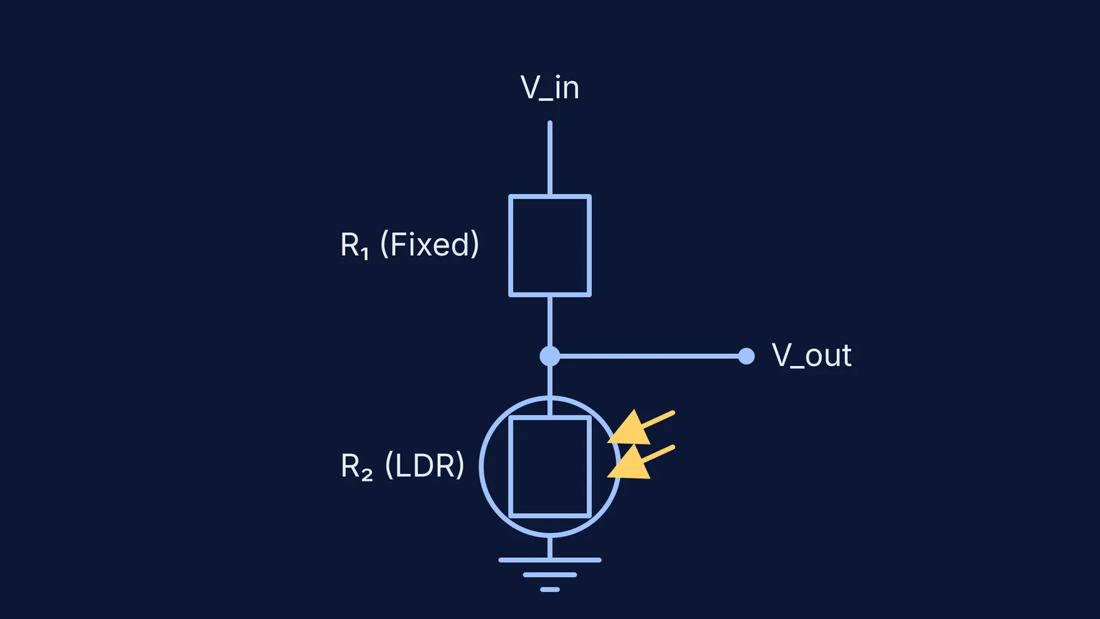
A standard potential divider consists of two resistors, R₁ and R₂, connected in series across a power supply (V_in). The output voltage (V_out) is usually taken across the second resistor, R₂.
The relationship is defined by the voltage divider equation: V_out = V_in × (R₂ / (R₁ + R₂))
This equation shows that the output voltage is a fraction of the input voltage, determined by the ratio of the two resistors. If R₂ changes while R₁ stays the same, V_out changes with it. This creates a bridge between the physical world and electronic logic. Instead of just passing a steady current, the circuit translates changes in light or temperature into a rising or falling electrical signal that other components can read.
How does an LDR work in a potential divider?
A Light Dependent Resistor (LDR), or photoresistor, is a semiconductor component that exhibits photoconductivity. When photons hit its sensitive surface, they give bound electrons enough energy to jump into the conduction band. The newly freed electrons allow the material to conduct electricity more easily.
This causes a massive shift in resistance. In the dark, an LDR can have a resistance as high as several megaohms (MΩ), while in bright light, it drops to a few hundred ohms.
If you place an LDR in the R₂ (bottom) position of a potential divider:
In darkness: The LDR's resistance is huge compared to R₁. Because it has the higher resistance, it takes the lion's share of the voltage, meaning V_out is high.
In bright light: The LDR's resistance collapses. It now takes a tiny fraction of the total voltage, so V_out drops near zero.
This setup is the brain behind automatic streetlights and garden lamps. When the sun sets and the output voltage rises past a certain threshold, a connected switching circuit detects the change and turns the main lights on.
How does an NTC thermistor respond to heat?
A thermistor is a resistor whose resistance varies strongly with temperature. The most common type encountered in school physics is the Negative Temperature Coefficient (NTC) thermistor.
Unlike a standard copper wire that gains slightly more resistance when heated, an NTC thermistor is made of semiconductor materials. As it heats up, it releases many more charge carriers. This overwhelming increase in free electrons means its resistance decreases as the temperature rises.
If you place an NTC thermistor in the R₂ position of a divider:
In a cold room: The thermistor has high resistance, making V_out high.
In a hot room: The thermistor's resistance falls sharply, making V_out low.
If you want a circuit that turns on an air conditioner or a cooling fan when a room gets too hot, you actually need the voltage to *rise* with temperature. To achieve this, simply swap the positions: place the thermistor in the R₁ position (top) and the fixed resistor in the R₂ position (bottom). As the thermistor's resistance drops in the heat, R₂ takes a larger share of the voltage, causing V_out to rise and trigger the cooling system.
Can you simulate a potential divider circuit?
Building these circuits in real life requires careful calculation to ensure the fixed resistor matches the sensor's working range. If you pair a 10 MΩ LDR with a 10 Ω fixed resistor, the output voltage will barely budge because the ratio is too extreme to provide a useful swing.
Testing different sensor values and observing the math is easier to see than read. You can open the Fermi Simulation Lab to predict how the output voltage changes when light falls on an LDR in a divider, then test sensors and resistor values interactively before you calculate them on paper. If you get stuck rearranging the voltage equation for a specific threshold, Fermi's AI tutor can work out what you already know and teach through the algebra, checking your understanding as it goes.
Planning a sensor circuit: a 3-step checklist
Identify the trigger: Decide if your circuit needs a high voltage in the light (LDR at top) or a high voltage in the dark (LDR at bottom).
Measure the extremes: Note the sensor's resistance in its "normal" state and its "triggered" state.
Choose the fixed resistor: Pick an R₁ value that sits roughly halfway between the sensor's high and low resistance states. This gives the widest possible voltage swing for the next part of your circuit to detect.
Once you have mastered single-sensor dividers, you might encounter more complex networks. Reading about the Node potential method: solving circuits by assigning voltages can help track how voltage drops across multiple branches, while exploring Stretching a wire: how its resistance changes with length shows how physical dimensions dictate the base resistance of standard components.