On this page
Your textbook gives two formulas. A simulation shows what they protect: a delicate coil, and a circuit that changes the moment you connect a meter. Predict the resistor values first, then test them.
What does converting a galvanometer into an ammeter or voltmeter mean?
A moving coil galvanometer is a coil in a magnetic field whose deflection is proportional to the current through it. The NCERT Class 12 Physics textbook, chapter 4 gives two reasons it cannot be used as an ammeter as it is: it gives a full-scale deflection for a current of the order of microamperes, and its own resistance, connected in series, would change the current it is trying to measure.
The fix is one extra resistor. A small shunt in parallel makes an ammeter, because most of the current goes through the shunt. A large resistance in series makes a voltmeter, because the meter then draws very little current from the circuit; NCERT says the usual aim is to keep that disturbance below one per cent.
How do you calculate the shunt and series resistance for a chosen range?
At full scale, exactly Ig flows through the coil, where Ig is the full-scale current and G is the coil's resistance; the circuits are Figures 4.21 and 4.22 of the NCERT chapter.
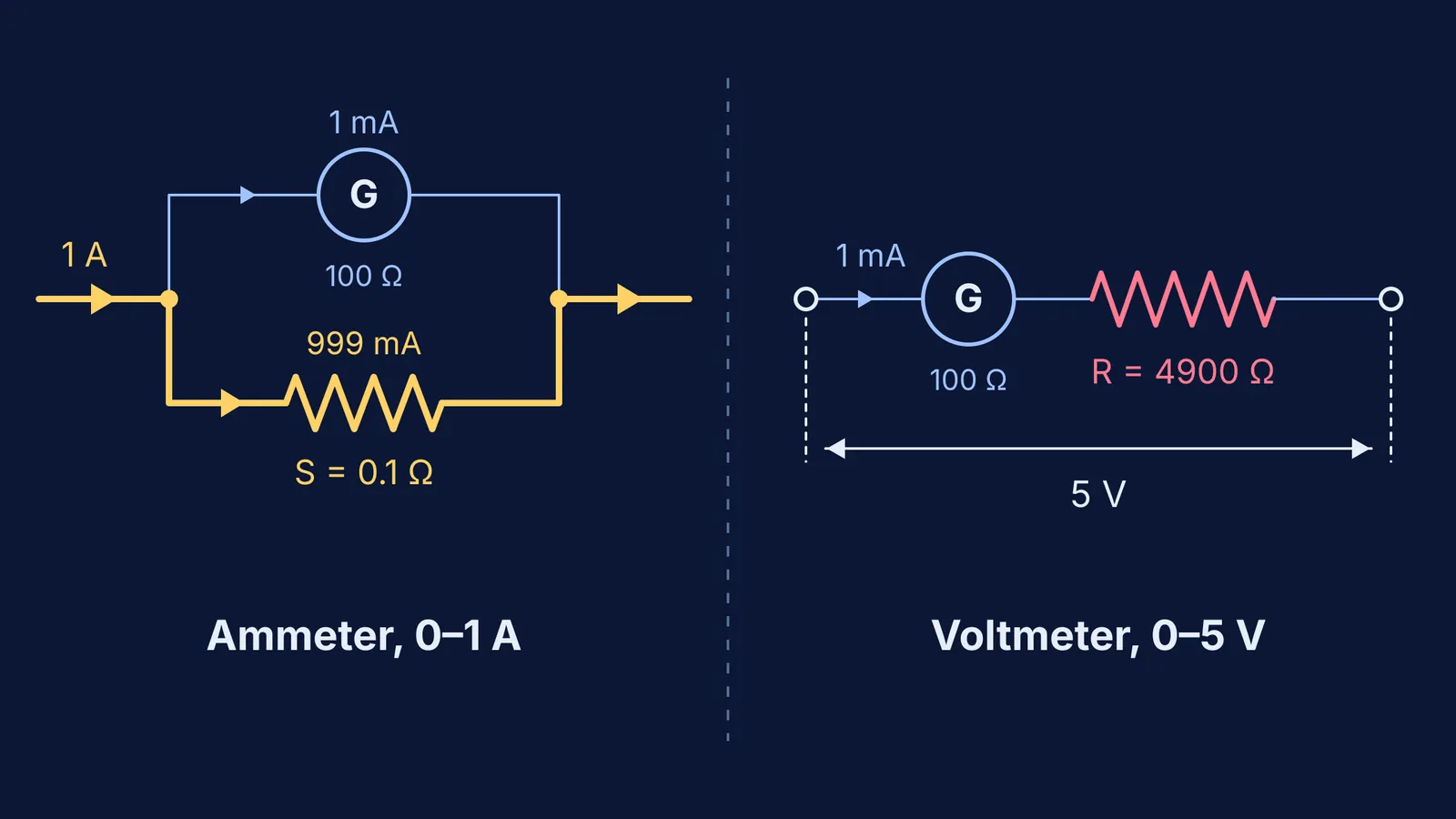
Ammeter, range 0 to I: coil and shunt S are in parallel, so they share a voltage: Ig × G = (I − Ig) × S, which gives S = Ig × G / (I − Ig).
Voltmeter, range 0 to V: coil and resistor R are in series, so V = Ig × (G + R), which gives R = V / Ig − G.
Worked example: take a practice galvanometer with G = 100 Ω and Ig = 1 mA (round numbers; NCERT's galvanometer is more sensitive still).
For a 0–1 A ammeter: S = (0.001 × 100) / (1 − 0.001) = 0.1 / 0.999 ≈ 0.100 Ω. The whole meter has a resistance of about 0.1 Ω, and 999 mA of every 1 A goes through the shunt.
For a 0–5 V voltmeter: R = 5 / 0.001 − 100 = 4,900 Ω. The whole meter has 5,000 Ω.
How do you test your prediction in a circuit simulation?
Any circuit simulation that lets you set resistor values and place meters will do. PhET's free Circuit Construction Kit: DC, from the University of Colorado, has batteries, resistors, wires and meters for current and voltage, and lets you change resistance values.
Model the galvanometer as a 100 Ω resistor. Put the simulator's ammeter in series with it and treat 1 mA through that branch as full scale.
Write down your predicted shunt, add it in parallel, and set up the circuit so 1 A flows into the combination.
Read the coil branch: close to 1 mA means your shunt is right. If the simulator cannot set 0.1 Ω, scale the range down: 0–10 mA needs S = 0.1 / 0.009 ≈ 11.1 Ω.
For the voltmeter, put your series resistor after the 100 Ω coil and connect both across a 5 V battery. The coil branch should read 1 mA. If one resistor cannot go high enough, chain several in series.
For more predict-then-test experiments, try these five DC circuit misconceptions to test in a simulation. The Fermi Simulation Lab has interactive simulations for the ideas that are easier to see than to read.
Why does an ammeter need low resistance and a voltmeter high resistance?
Because a meter becomes part of the circuit. In Example 4.12 of the NCERT chapter, a 3.00 V source drives current through a 3.00 Ω resistor, so the true current is 1.00 A. With a 60 Ω galvanometer in series the current falls to 0.048 A; converted with a 0.02 Ω shunt, the meter reads 0.99 A.
Our 0.1 Ω ammeter in that circuit would read 3 / 3.1 ≈ 0.97 A, about 3% low. The bare 100 Ω galvanometer would pass 3 / 103 ≈ 29 mA, which is still 29 times its full-scale current.
A voltmeter sits in parallel, so it steals current instead. Connect a 4 V battery across two equal resistors in series; the true voltage across each is 2 V. Now measure one of them with the 5,000 Ω voltmeter:
Two 100 Ω resistors: it reads about 1.98 V, roughly 1% low.
Two 1,000 Ω resistors: about 1.82 V, roughly 9% low.
Two 10,000 Ω resistors: 1.00 V, half the true value.
The rule: an ammeter must be small compared with the resistance in series with it, and a voltmeter large compared with the resistance it sits across. Our post on how non-ideal ammeters and voltmeters change circuit readings works through more cases.
If a step stops making sense, Fermi's AI tutor can run the simulation with you, draw the figure and check your understanding as it goes.