On this page
Capacitor combinations look easy because there are only two formulas to learn. What usually trips people up is the follow-up question: which capacitor holds more charge, and which one takes more voltage? A simulation lets you guess first and then check, so the rules come from what you saw on the screen, not just what you memorised.
What are the rules for capacitors in series and parallel?
Capacitance is the charge a capacitor stores divided by the voltage across its plates, C = Q/V, as defined in OpenStax University Physics Volume 2, section 8.1. One farad is one coulomb per volt.
The four rules below are from OpenStax section 8.2 on capacitors in series and in parallel:
Series: all capacitors in a series combination have the same charge, because charge is conserved along the chain.
Series total: 1/C = 1/C1 + 1/C2 + 1/C3 + ..., and the equivalent capacitance is always less than the smallest individual capacitance.
Parallel: all capacitors in parallel have the same voltage across their plates.
Parallel total: C = C1 + C2 + C3 + ..., so capacitances simply add.
OpenStax works one example each way: 1, 5 and 8 µF capacitors give 0.755 µF in series and 14.0 µF in parallel (OpenStax 8.2). Notice that the series answer is smaller than even the 1 µF capacitor.
Which capacitor takes more voltage in series?
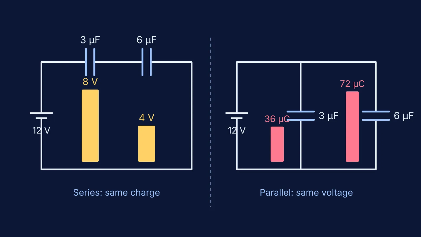
The one with the smaller capacitance. Each capacitor in a series chain carries the same charge Q, so the voltage across each is V = Q/C, and a smaller C means a bigger V. Take a 3 µF and a 6 µF capacitor in series across a 12 V battery:
Total capacitance: 1/C = 1/3 + 1/6 = 1/2, so C = 2 µF.
Charge: Q = CV = 2 µF × 12 V = 24 µC, the same on both capacitors.
Voltages: 24/3 = 8 V across the 3 µF and 24/6 = 4 V across the 6 µF. These add up to 12 V, as they should.
If you guessed that the bigger capacitor takes more of the voltage, the voltmeter in the simulation will show you it takes less.
Which capacitor holds more charge in parallel?
The one with the larger capacitance. In parallel, both capacitors see the full 12 V, so Q = CV gives 3 × 12 = 36 µC on the 3 µF and 6 × 12 = 72 µC on the 6 µF. The battery supplies 108 µC in total, which is exactly what the 9 µF equivalent capacitance predicts (9 × 12 = 108).
Energy follows the same pattern. OpenStax gives the stored energy as U = ½QV = ½CV² = Q²/2C (OpenStax 8.3). In the series circuit above, the 3 µF stores ½ × 24 × 8 = 96 µJ and the 6 µF stores 48 µJ, so the smaller capacitor stores more. In parallel it is the other way round.
How do you test capacitor predictions in a simulation?
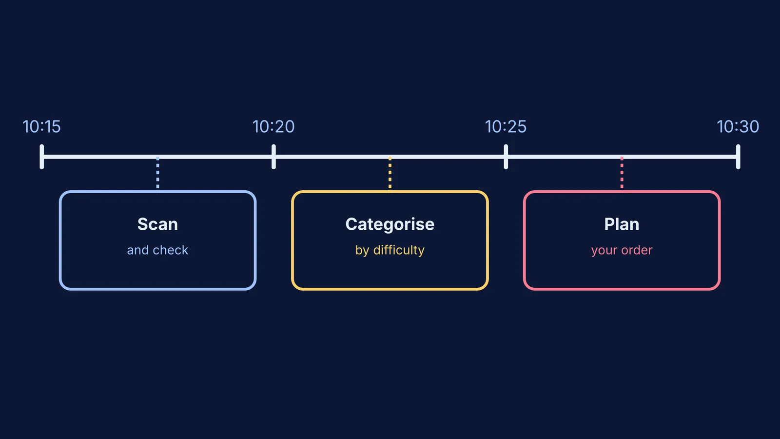
Use predict, run, explain. Write your guess down before you touch anything; that way the simulation can actually surprise you. Our post on testing five DC circuit misconceptions with a simulation uses the same routine for resistors, and what PhET research says simulations are good for explains why guessing first matters.
Series test. Build 3 µF and 6 µF in series on 12 V. Predict which has more charge and which has more voltage. Measure both.
Parallel test. Rewire the same two in parallel. Predict the charge on each and the total. Measure.
Mixed test. Put 6 µF in series with a parallel pair of 2 µF and 4 µF, on 12 V. The pair adds to 6 µF, so the total is 3 µF, Q = 36 µC, and each section gets 6 V. Then the 2 µF holds 12 µC and the 4 µF holds 24 µC. Predict before you measure.
Explain. For every prediction you got wrong, write one sentence saying which rule you broke.
PhET's free Capacitor Lab simulation is one place to try these tests.
The Fermi Simulation Lab has interactive simulations for ideas that are easier to see than to read. Fermi's AI tutor can run the simulation and check your understanding as it goes, deciding whether to explain, ask or show.
Next, try circuits where capacitors sit beside resistors, with our guide to capacitors in DC circuits at steady state.