On this page
Why did early dynamos fail to produce steady current?
After Michael Faraday demonstrated electromagnetic induction in 1831, early generators such as Hippolyte Pixii's 1832 magneto and Werner von Siemens's 1856 shuttle armature spun a single coil between opposite magnetic poles. As you learn in Faraday's and Lenz's laws of electromagnetic induction, a single rotating loop produces an alternating electromotive force that drops through zero volts twice during every single rotation (Encyclopaedia Britannica).
Rectifying this output with a split-ring commutator yielded direct current, but with severe pulsation. Voltage repeatedly surged and dropped to zero, sparking heavily at collection brushes and overheating windings. For nineteenth-century electroplating baths and arc lighting, pulsating current was unusable.
How does the Gramme ring armature generate continuous DC?
The solution came from Zénobe-Théophile Gramme, a Belgian craftsman who moved to Paris in 1856 (Encyclopaedia Britannica). In 1869, Gramme designed a closed-loop ring armature, presented by French physicist Jules Jamin to the Académie des Sciences in Paris on July 17, 1871 (Encyclopaedia Britannica).
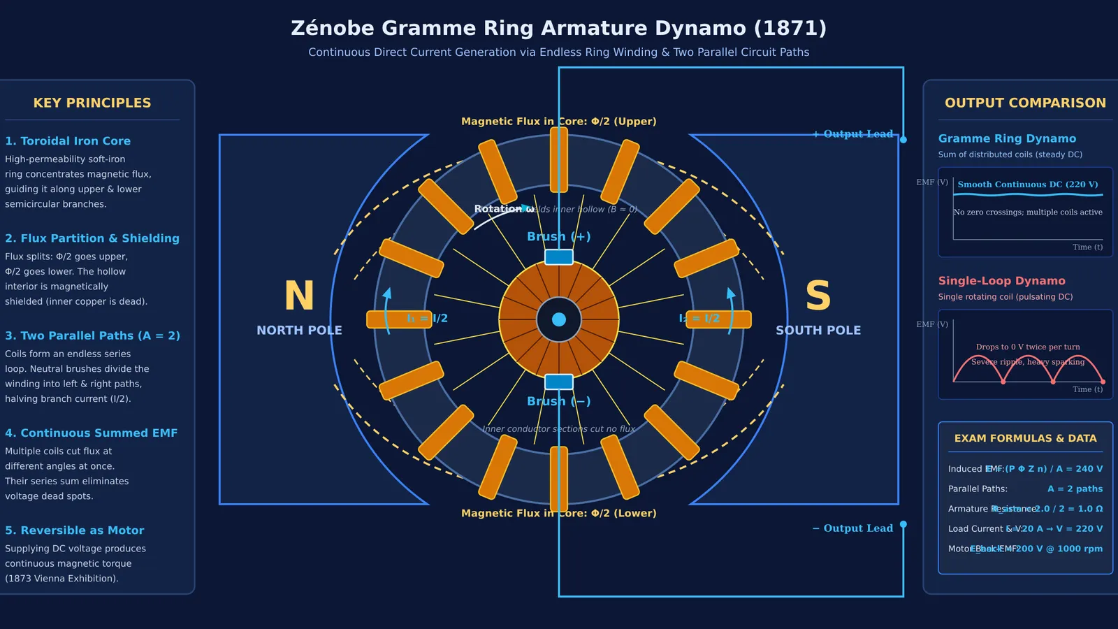
As detailed in an 1875 review of magneto-electric machines in Nature, Gramme wound an unbroken series of copper coils around a soft-iron ring, tapping each coil junction to an insulated segment on a cylindrical commutator. Two stationary brushes pressed against the commutator at the neutral plane, dividing the winding into two symmetrical parallel paths:
The left semicircular path connected all series coils facing the North pole.
The right semicircular path connected all series coils facing the South pole.
Both paths joined in parallel across the brushes at the neutral plane, sharing the total load current equally.
Because multiple coils were distributed around the ring, several coils cut magnetic flux at their peak angle simultaneously. As one coil turned past the neutral plane, another immediately replaced it. Summing these series voltages along each parallel branch produced smooth, continuous direct current.
How was the Gramme dynamo discovered to be an electric motor?
Gramme designed his machine as a generator, but its operation as an industrial motor was discovered publicly at the 1873 Vienna World Exhibition (Encyclopaedia Britannica).
Gramme's partner Hippolyte Fontaine, who later authored a treatise on Electrolysis, set up two dynamos in the exhibition hall. While testing the equipment on June 3, 1873, Fontaine connected a generator driven by a gas engine across long cables to a second, stationary machine. When current entered the second armature, the magnetic field exerted torque on the coils, causing the armature to spin as an electric motor.
Fontaine used the motor to power a centrifugal water pump, demonstrating long-distance power transmission for the first time. In 1880, Scottish physicist Peter Guthrie Tait published measurements of Gramme dynamo voltage across varied speeds in the Proceedings of the Royal Society of Edinburgh. Proving that dynamos were reversible paved the way for modern factories, Nikola Tesla's alternating current induction motors, and modern AC generators and transformers.
How do you calculate EMF and current in a ring armature?
To see how the ring armature behaves in competitive physics exams, consider a 2-pole Gramme dynamo evaluated using principles reported in the Proceedings of the Royal Society of Edinburgh:
Magnetic flux per pole: Φ = 0.025 Wb
Speed: 1200 rpm (rotational frequency n = 20 rev/s)
Total active conductors: Z = 480 (24 coils of 20 turns each)
Parallel paths: A = 2
Total winding resistance: R_total = 4.0 Ω
The induced electromotive force (EMF) across the brushes is: E = (P × Φ × Z × n) / A = (2 × 0.025 × 480 × 20) / 2 = 240 V
Because the two semicircular halves are in parallel, each branch has a resistance of 2.0 Ω. The net armature resistance is: R_armature = 2.0 / 2 = 1.0 Ω
When delivering a load current of I_total = 20 A:
Each branch carries half the current: I_branch = 20 / 2 = 10 A
Terminal voltage is: V = E − (I_total × R_armature) = 240 − (20 × 1.0) = 220 V
When supplied as a motor with a 220 V source while running under load at 1000 rpm, the armature generates an opposing back-EMF: E_back = 240 × (1000 / 1200) = 200 V
The resulting motor current is governed by the net voltage across the armature resistance: I_motor = (V − E_back) / R_armature = (220 − 200) / 1.0 = 20 A
Students exploring how back-EMF governs DC motor current can observe interactive coil simulations in the Fermi Simulation Lab. For numerical practice on parallel paths and internal resistance, the Fermi Problem Library has worked problems with a step-by-step solver that explains the reasoning rather than printing an answer.
What made the drum armature replace the Gramme ring?
Despite its success, the Gramme ring had an architectural inefficiency analyzed in Nature.
Because the iron ring concentrates magnetic flux within itself, the inner hollow is shielded from magnetic lines of force. Wire threaded through the inside of the ring cuts no flux, contributing roughly 50% of the copper resistance and wasting energy as Joule heat without producing voltage.
In 1872, Friedrich von Hefner-Alteneck introduced the drum armature for Siemens & Halske. By winding coils exclusively on the outer cylindrical surface, all conductors cut magnetic flux, doubling active copper efficiency and creating the standard used in modern DC machines.