On this page
Why did Nikola Tesla invent the coil in 1891?
In the spring of 1891, Nikola Tesla filed U.S. Patent No. 454,622 for a "System of Electric Lighting", granted on 23 June 1891. Weeks earlier, on 20 May 1891, he presented the apparatus before the American Institute of Electrical Engineers at Columbia College in New York, published in the *Transactions of the AIEE*. Tesla wanted to explore alternating currents at frequencies far higher than the 50 Hz or 60 Hz used for municipal grids. Studying wireless lighting with gas-discharge tubes required high potentials oscillating at hundreds of thousands of cycles per second.
Earlier devices like Nicholas Callan's early induction coil relied on iron cores and mechanical interrupters. While effective at low frequencies, iron cores failed at radio frequencies: rapid magnetic reversals created intense eddy currents and hysteresis heating that melted insulation. Tesla solved this by discarding the iron core entirely, creating an air-core transformer governed by resonance.
How does a resonant transformer differ from a normal transformer?
In conventional iron-core transformers, coils share a closed ferromagnetic core that produces tight magnetic coupling. Magnetic flux remains almost entirely confined within the iron, stepping up voltage across a single half-cycle according to turns ratio: V₂ / V₁ ≈ N₂ / N₁.
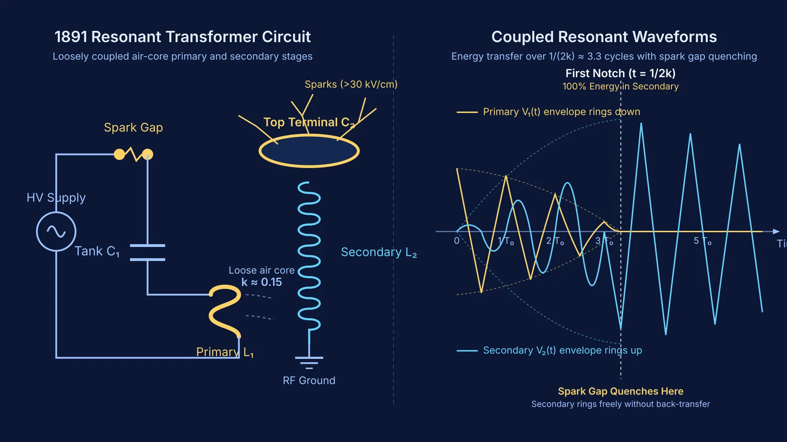
A Tesla coil operates on a completely different principle: coupled resonance. As Kenneth D. Skeldon, Alastair I. Grant, and Steven A. Scott detail in the *American Journal of Physics*, a Tesla coil is an air-core resonant transformer with loose magnetic coupling, where the coupling coefficient k typically falls between 0.1 and 0.2 (compared to near 1.0 in iron-core units). Because the coils share open air, magnetic flux leaks freely, and secondary voltage builds gradually over multiple cycles like a swing pushed in time with its natural period.
The circuit pairs two tuned stages:
A primary tank: a high-voltage supply charges capacitor C₁ until a spark gap fires, discharging C₁ through primary inductor L₁.
A secondary coil: a tall coil L₂ grounded at its base and topped with a smooth toroid providing terminal capacitance C₂.
When tuned to the same frequency, f₀ = 1 / (2π√(L₁C₁)) = 1 / (2π√(L₂C₂)), the condition L₁C₁ = L₂C₂ produces resonance.
How does energy transfer between the coupled circuits?
When the spark gap fires, ionized air creates a conductive bridge that triggers LC oscillations and energy swapping in the primary tank. Initially, all stored energy E = (1/2)C₁V₁² sits in the primary capacitor.
As Kenneth D. Skeldon and colleagues describe in the *American Journal of Physics*, mutual inductance M = k√(L₁L₂) transfers energy between the loosely coupled inductors over roughly 1 / (2k) cycles. For a typical coupling coefficient of k = 0.1, complete energy transfer takes approximately 5 cycles. The primary voltage envelope rings down toward zero, while the secondary voltage envelope rings up toward a tall resonant peak.
When the primary voltage reaches zero—the first notch—all energy has migrated into the secondary. If the spark gap quenches at this moment, energy cannot return to the primary. The secondary coil rings freely at frequency f₀, concentrating charge on the top terminal.
Worked example: how do you calculate secondary voltage?
Because a resonant transformer steps up voltage through energy conservation rather than turns ratio, you calculate peak secondary voltage from stored electrical energy: (1/2) C₁ V₁² ≈ (1/2) C₂ V₂²
Rearranging gives: V₂ ≈ V₁ × √(C₁ / C₂)
Because L₁C₁ = L₂C₂ at resonance, C₁ / C₂ = L₂ / L₁, so V₂ ≈ V₁ × √(L₂ / L₁).
Consider the replica apparatus parameters documented by James B. Kelley and Lee Dunbar in the *American Journal of Physics*:
Primary capacitor: C₁ = 10 nF (10 × 10⁻⁹ F), charged by a 15 kV supply transformer until the spark gap fires at V₁ = 15 kV (15,000 V), storing E = (1/2) × (10 × 10⁻⁹ F) × (15,000 V)² ≈ 1.1 J.
Secondary terminal capacitance: C₂ ≈ 25 pF (25 × 10⁻¹² F) provided by the secondary winding self-capacitance and top discharge terminal.
Capacitance ratio: C₁ / C₂ = (10 × 10⁻⁹ F) / (25 × 10⁻¹² F) = 400.
Voltage gain: √(C₁ / C₂) = √400 = 20.
Secondary voltage: V₂ ≈ 15 kV × 20 = 300 kV (300,000 V).
According to standard dielectric strength measurements, dry air breaks down at an electric field of roughly 30 kV/cm (3 MV/m). A terminal energized to 300 kV establishes local electric field gradients far exceeding 30 kV/cm, creating visible ionization and producing the 12-inch (roughly 30 cm) spark discharges documented in Kelley and Dunbar's replica.
Visualizing energy swapping in resonant circuits can feel abstract. Interactive simulations in the Fermi Simulation Lab show ideas that are easier to see than to read, letting you observe energy swapping between coupled coils as inductance, capacitance, and coupling vary. When calculating resonance and voltage gain, the Fermi Problem Library offers worked problems with a step-by-step solver that explains the reasoning rather than printing an answer.
What happened to the Tesla coil after 1891?
Tesla viewed his resonant transformer as the foundation for wireless power and communication. In the late 1890s, he adapted the spark-excited circuit into transmitters for wireless telegraphy. Early transatlantic radio systems used spark-gap resonant oscillators based on Tesla's 1891 circuit to drive large antennas.
While modern radio transmitters replaced spark gaps with transistors, the principles of resonant tuning, loose air-core coupling, and LC energy transfer remain central across electrical engineering. Whenever you solve coupled LC resonance problems in Class 12 physics, you are working with the resonant transformer principles Nikola Tesla introduced in 1891.