On this page
In the late 1890s, long-distance telephony stalled because voice signals degraded after 30 miles of underground cable or a few hundred miles of overhead wire. In December 1899, Serbian-American physicist Mihajlo Pupin solved the problem by patenting lumped inductance coils placed at periodic intervals along telephone wires, granted as U.S. Patent 652,230. Pupin's coils cut signal dissipation, keeping audio frequencies aligned and quadrupling network range while saving millions in copper wire.
Why did long-distance telephone lines lose their voice?
Telephone lines carry complex alternating waves spanning voice frequencies from 300 Hz to 3,400 Hz. A two-wire line has four primary constants per unit length: resistance R, series inductance L, capacitance C, and leakage conductance G, as analyzed in Pupin's 1899 mathematical study.
In Pupin's 1899 line formulation, line insulation keeps leakage G near zero, but inductance L is tiny while capacitance C is substantial. When resistance dominates inductive reactance (ωL ≪ R), the attenuation constant follows α ≈ √(ωRC/2):
Energy dissipation: signal voltage decays as e^(−αx), losing power into heat.
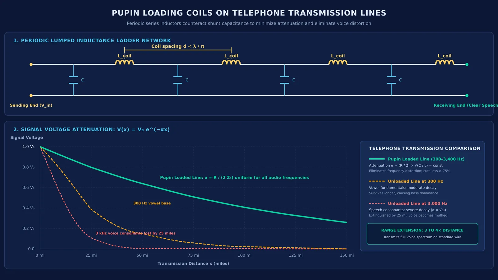
Frequency distortion: because α scales with √ω, consonants at 3,000 Hz attenuate 3.16 times faster per mile than vowel fundamentals at 300 Hz.
In Pupin's artificial cable experiments, high frequencies vanished after 25 miles of cable, leaving speech an unintelligible rumble. Oliver Heaviside had shown in 1887 that R/L = G/C eliminated distortion, but continuously wrapping wire in iron was commercially impractical.
How do loading coils reduce signal attenuation on telephone wires?
Pupin realized that deliberately increasing line inductance L raises characteristic impedance, Z₀ = √(L/C). Because transmitted power obeys P = V × I ≈ I² Z₀, higher impedance carries speech energy with higher voltage and lower current I.
Lower current reduces Joule heating losses in copper (P_loss = I²R). With sufficient inductance such that ωL ≫ R, attenuation simplifies to: α ≈ (R / 2) × √(C / L) = R / (2 Z₀) as Pupin showed in his 1900 mathematical analysis. Inductance L in the denominator keeps attenuation low and uniform across voice frequencies.
What was Mihajlo Pupin's vibrating string breakthrough?
Engineers feared lumped coils would reflect and scatter signals. Pupin, who immigrated in 1874 and became a Columbia University professor (Columbia University C250 Profile), resolved this with classical mechanics.
He studied Lagrange's 1788 model of a string loaded with periodic masses. When mass spacing is much smaller than vibrational wavelength, the string behaves like a continuous heavy string. Pupin identified an exact electrical analogue: mass corresponds to inductance L, tension to reciprocal capacitance 1/C, and friction to resistance R.
In Pupin's 1900 experimental paper, he proved that inserting coils of inductance L_coil at spacing d with at least π coils per wavelength (practically 8 to 10 coils per wavelength for speech) makes the line act like a continuous cable. He verified this on an artificial cable simulating 250 miles of wire.
AT&T acquired Pupin's patent rights in 1900–1901, as recorded by the National Inventors Hall of Fame. Termed "pupinization," the technique extended signal reach 3 to 4 times without thicker wire, saving telephone networks tens of millions of dollars in copper. Later, engineer Edith Clarke expanded transmission line calculations to stabilize electric grids.
How do engineers calculate loading coil spacing?
A line with periodic coils forms a low-pass filter, analyzed by George Campbell in 1903. Above cutoff frequency f_c, signals reflect back: f_c = 1 / (π × √(L_coil × C × d))
Worked example: Designing a loaded telephone circuit In Campbell's 1903 filter study, suppose a cable has capacitance C = 0.052 μF/mile (5.2 × 10⁻⁸ F/mile). For coils of L_coil = 88 mH (0.088 H) and cutoff safety threshold f_c = 4.4 kHz:
Isolate spacing d:
d = 1 / (π² × f_c² × L_coil × C)
Substitute the values:
d = 1 / (3.1416² × 4,400² × 0.088 × 5.2 × 10⁻⁸) ≈ 1.14 miles (approximately 6,000 feet)
Placing an 88 mH coil every 6,000 feet (known as "H-88 loading") transmits voice up to 3.4 kHz while cutting attenuation by over 75% compared to unloaded wire, matching Campbell's 1903 paper.
If you are exploring how inductors and capacitors store and swap energy in Class 12 alternating current circuits, the Fermi Simulation Lab provides interactive simulations for the ideas that are easier to see than to read.
What can Class 12 and JEE students learn from transmission lines?
For students preparing for JEE Advanced or CBSE Class 12 physics, Pupin's work connects textbook electromagnetism to real engineering:
Inductive reactance: Inductors oppose alternating current, with reactance rising with frequency. Studying self and mutual inductance in coils clarifies energy storage in magnetic fields.
Mechanical analogues: Equating mass to inductance and spring elasticity to capacitance unifies mechanical and electrical oscillations.
Distributed circuits: When line length approaches signal wavelength, circuits must be analyzed as distributed transmission lines rather than lumped components.
Pupin's research guided future pioneers, including his student Edwin Armstrong and his invention of FM radio.
To practise alternating current, resonance, and inductor network problems for competitive exams, the Fermi Problem Library offers worked problems with a step-by-step solver that explains the reasoning rather than printing an answer.