On this page
In 1765, a 19-year-old draftsman named Gaspard Monge was given a difficult assignment at the École Royale du Génie at Mézières. He had to design a fortification plan that would shield a military position from enemy view and fire, regardless of where the enemy stood. Instead of relying on the cumbersome arithmetic of the time, Monge applied his own mathematical theories to create a graphical method for solving the complex three-dimensional problem.
His technique was so fast and precise that it revealed a completely new mathematical tool. For years, Monge's methods were taught at military engineering schools. It was not until the French Revolution, when Monge helped found the École Polytechnique, that his methods were finally published in his 1799 textbook *Géométrie descriptive*.
How does descriptive geometry work?
Monge's goal was to capture the exact dimensions, angles and intersections of complex solid objects on a standard, two-dimensional sheet of paper.
He achieved this through a system of orthographic projection. By projecting every point of a 3D object onto two perpendicular planes — typically a horizontal plane and a vertical plane — a draftsman can create a precise representation of the shape.
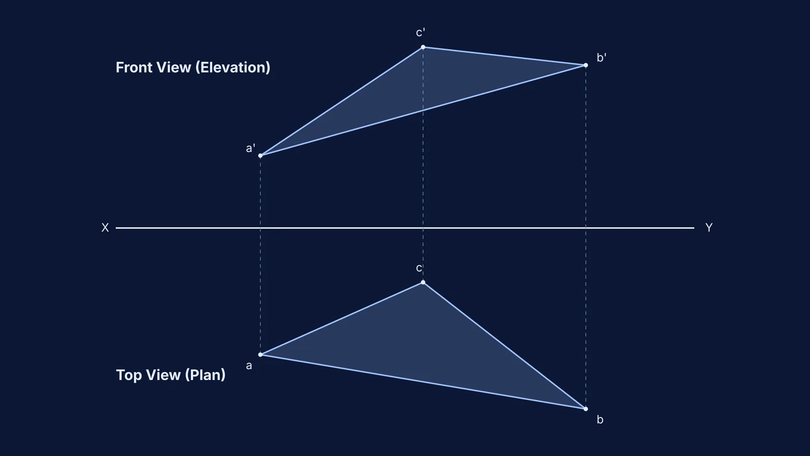
The genius of Monge's method lies in how these planes are handled on paper. Once the views are projected, the horizontal plane is rotated flat around the intersecting axis (known as the ground line) until it aligns perfectly with the vertical plane. The result is two views of the same object stacked on a single page, with projection lines connecting the corresponding points. This allows an engineer to calculate the true length of slanted lines and the true shape of angled surfaces without ever needing to build a physical model.
Why is descriptive geometry important today?
Descriptive geometry became the foundation of all mechanical drawing and architecture across the world. The need for precise, interchangeable parts drove the adoption of these strict rules, formally cementing Monge's projection principles into modern industry.
While today's engineers rely on Computer-Aided Design (CAD) software rather than a pencil and a T-square, the underlying logic remains unchanged. Every time a designer switches a digital model between a plan view and an elevation, they are relying on the mathematical rules Monge laid out over two centuries ago. The software handles the drawing, but the engineer must still understand the spatial logic of the projections to ensure the parts fit together.
Visualising these spatial relationships can be difficult when learning physics or advanced mathematics. If you struggle to picture intersecting planes or complex fields, the Fermi Simulation Lab provides interactive simulations for the ideas that are easier to see than to read.
How does this framework help you think in 3D?
When you encounter complex spatial problems in exams — such as tracking motion in a plane or dividing segments using the section formula in 3D — it helps to break the object down into Monge's standard views.
To sketch a reliable drawing, isolate the three primary angles:
Top View (Plan): Look straight down from above. This reveals the true width and depth of the object, ignoring its height completely.
Front View (Elevation): Look straight at the object from the front. This shows the true width and height, ignoring depth.
Side View (Profile): Look from the left or right side. This provides the true depth and height.
By sketching these two-dimensional views and aligning them with dashed projection lines, you can uncover hidden details and safely calculate angles and distances. Mastering this method wires the brain for three-dimensional thinking, long before a computer does the work for you. If you are working through 3D geometry or vectors for exams and aren't sure how to begin, the Fermi Problem Library has worked problems with a step-by-step solver that explains the reasoning rather than printing an answer.