

On this page
What happens when the source slit is shifted off-axis?
In a standard textbook setup, such as the one described in NCERT Class 12 Physics Chapter 10 on Wave Optics, Young's double-slit experiment places the primary source slit S symmetrically along the perpendicular bisector of two narrow slits, S₁ and S₂. Because S is equidistant from both slits, cylindrical wavefronts arrive at S₁ and S₂ in phase. The geometric centre of the screen, point O, lies equidistant from both slits. Consequently, the two secondary waves arrive at point O with zero optical path difference, forming the bright central maximum (zero-order fringe).
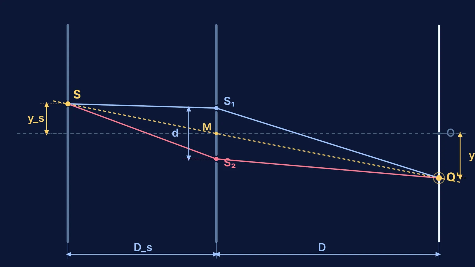
When you displace the source slit S vertically by a distance y_s perpendicular to the central axis, that initial symmetry breaks. Light now has to travel unequal paths before it even reaches the double slits. As documented in Thomas Young's 1804 Bakerian Lecture, wave interference depends entirely on the net optical path accumulated across the entire journey from the source to the observer. Shifting the source introduces a pre-slit path difference that alters where the zero-difference condition is satisfied on the screen.
Understanding this shift connects directly to Thomas Young's discovery of wave interference and remains a staple problem in competitive exams like JEE Advanced.
Why does the central fringe shift in the opposite direction?
To see why the central fringe moves opposite to the source, follow the light along both paths. Suppose the source slit S sits at a distance D_s from the double-slit plane, the two slits are separated by distance d, and the screen is at distance D.
If you shift the source slit upward by +y_s towards S₁, the distance S S₁ becomes noticeably shorter than S S₂. Using the small-angle approximation, the path difference introduced between the source and the two slits is:
Δx_source = S S₂ - S S₁ ≈ d × (y_s / D_s)
Because light heading to S₂ travels a longer path, the wave emerging from S₂ lags behind the wave emerging from S₁. For the central maximum to form at a point P at height y on the observation screen, the total path difference across both stages must sum to zero:
Δx_total = (S S₂ - S S₁) + (S₂ P - S₁ P) = 0
Since (S S₂ - S S₁) is positive (+d y_s / D_s), the post-slit path difference (S₂ P - S₁ P) must be negative to cancel it out. This means point P must lie closer to S₂ than to S₁. On the screen, that requires moving below the central axis (y < 0):
S₂ P - S₁ P ≈ d × (y / D)
Setting the total path difference to zero:
d × (y_s / D_s) + d × (y / D) = 0
Solving for the central fringe position y₀ yields:
y₀ = - (D / D_s) × y_s
The negative sign is the mathematical proof of the inversion: moving the source upward forces the central maximum downward. This cancellation is a practical application of converting phase difference to path difference.
Does shifting the source slit change the fringe width?
A frequent trap in mock tests is assuming that moving the source stretches or compresses the interference pattern. It does not.
The fringe width β represents the spatial separation between any two consecutive bright fringes (or two consecutive dark fringes). To find the position of the n-th bright fringe y_n, set the total path difference equal to an integer multiple of the wavelength λ:
Δx_total = d × (y_s / D_s) + d × (y_n / D) = nλ
Rearranging for y_n gives:
y_n = n × (λD / d) - (D / D_s) × y_s
Now find the separation between fringe (n + 1) and fringe n:
β = y_(n+1) - y_n = [ (n + 1) × (λD / d) - (D / D_s) × y_s ] - [ n × (λD / d) - (D / D_s) × y_s ]
β = λD / d
The source displacement term cancels out completely. As detailed in our review of Young's double-slit experiment problem patterns, the fringe width β depends solely on λ, D, and d. The entire pattern of alternating bright and dark bands shifts as a rigid ruler across the screen.
How do you solve an off-axis source problem step by step?
When approaching questions in JEE Main or JEE Advanced based on the NCERT Class 12 Physics syllabus, follow this four-step procedure.
Worked Problem: A double-slit setup uses yellow light of wavelength λ = 600 nm (6.0 × 10⁻⁷ m). The slit separation is d = 1.0 mm (1.0 × 10⁻³ m), the source slit sits at distance D_s = 0.50 m in front of the slits, and the screen sits at D = 1.50 m behind them. If the source slit is moved upward by y_s = 1.0 mm, determine the position of the central maximum and the number of fringe widths shifted.
Compute the standard fringe width:
β = λD / d = (6.0 × 10⁻⁷ m × 1.50 m) / (1.0 × 10⁻³ m) = 9.0 × 10⁻⁴ m = 0.90 mm.
Determine the linear shift of the central maximum:
y₀ = - (D / D_s) × y_s = - (1.50 m / 0.50 m) × 1.0 mm = - 3.0 × 1.0 mm = - 3.0 mm. The central fringe shifts 3.0 mm downward.
Calculate the number of fringes shifted:
Number of fringes N = |y₀| / β = 3.0 mm / 0.90 mm = 3.33 fringe widths (or 10/3 fringes).
Verify path compensation at the new central maximum:
Before the slits, the extra path is Δx_source = d × y_s / D_s = (1.0 × 10⁻³ m × 1.0 × 10⁻³ m) / 0.50 m = 2.0 × 10⁻⁶ m = 2000 nm. After the slits at y = -3.0 mm, the path difference is Δx_screen = d × y / D = (1.0 × 10⁻³ m × (-3.0 × 10⁻³ m)) / 1.50 m = - 2.0 × 10⁻⁶ m = - 2000 nm. Net path difference Δx_total = 2000 nm - 2000 nm = 0 nm, confirming constructive zero-order interference.
What happens if the source slit is widened instead of shifted?
A natural follow-up question concerns what happens when the source slit is widened rather than shifted. According to NCERT Class 12 Physics on wave optics, a wide source slit behaves like an array of independent point sources placed side by side.
Each point across the width of the source produces its own interference pattern on the screen. Because each point sits at a slightly different off-axis position, its pattern is shifted by a corresponding amount. For sharp interference fringes to remain visible, the source slit width s must satisfy the coherence condition:
s / D_s < λ / d
If the source slit becomes wider than λD_s / d, the bright fringes from one edge fall directly on the dark fringes from another edge. The overlapping patterns wash each other out, leaving only uniform illumination on the screen.
When tackling multi-slit questions and optical path shifts, having the right practice environment makes a decisive difference. The Fermi Problem Library offers worked problems with a step-by-step solver that explains the reasoning rather than printing an answer. If you are reviewing the foundational principles of wave optics, the Fermi Concept Library maps every concept in physics, chemistry, biology, mathematics and computing, each with its own lesson and its place in the map. When you need targeted support, Fermi's AI tutor can work out what you already know and build a plan for the session, guiding you through sign conventions and ray geometry before your next exam.


