

On this page
Every time you open a bathroom faucet, water rushes out without an electric motor humming in the background. That silent, instantaneous flow is driven entirely by the vertical elevation of the water stored above you. In fluid statics, pressure is defined as the normal force exerted per unit area over a surface according to OpenStax University Physics Volume 1. Within any continuous, resting liquid of uniform density, pressure increases linearly with vertical depth beneath the free surface through the relation P = P₀ + ρgh. In this formula, P₀ represents atmospheric pressure acting on the open surface, ρ is the fluid density, g is the acceleration due to gravity, and h is the vertical depth of the water column.
How does water height create pipe pressure?
Because atmospheric pressure acts equally on the open water surface in the overhead tank and against the open discharge mouth of your household faucet, atmospheric pressure cancels across the open plumbing circuit. What propels the fluid forward through the pipe is the gauge pressure, given by ΔP = ρgh, as explained by OpenStax University Physics Volume 1. Under standard conditions, liquid water has a density of approximately 1,000 kilograms per cubic metre, and the standard acceleration of gravity is 9.80665 metres per second squared according to the NIST Reference on Constants, Units, and Uncertainty. Multiplying these physical constants shows that every single vertical metre of water head generates approximately 9.8 kilopascals (0.098 bar) of hydrostatic gauge pressure.
Crucially, this hydrostatic pressure depends strictly on the vertical depth h, rather than the shape of the tank, the diameter of the riser pipe, or the total volume of stored water. Whether a pipe runs straight down or winds through dozens of bends, the static pressure at any point is governed strictly by the vertical distance below the tank's water level. For students preparing for mechanics, this foundational principle connects directly to classic problems in hydrostatic pressure and depth problems.
Why does tap pressure vary across different floors?
If you have ever showered on the top floor of a house and noticed a weak trickle while the ground-floor tap produces a forceful jet, you have observed hydrostatic head in action. The top floor sits closest to the overhead tank, meaning its vertical height difference h is minimal. By contrast, fixtures on lower storeys sit beneath a much taller vertical column of water. Under the hydrostatic formula P = ρgh verified by OpenStax University Physics Volume 1, a tap located 10 metres below the roof tank receives nearly 98 kilopascals of static gauge pressure, whereas a shower located only 1.5 metres below the tank bottom receives less than 15 kilopascals.
To prevent inadequate flow at upper fixtures, national engineering standards prescribe minimum pressure thresholds for residential buildings. Under the Bureau of Indian Standards code IS 2065:1983 (Code of Practice for Water Supply in Buildings), plumbing systems must deliver a minimum residual head of 0.018 newtons per square millimetre (equivalent to 1.8 metres of head, or 18 kilopascals) at the highest and most remote draw-off tap. When internal pipe networks transmit fluid pressure uniformly across enclosed junctions, they follow the fundamental rule of Pascal's law in hydraulic machines.
Worked example: calculating tap pressure in a two-storey house
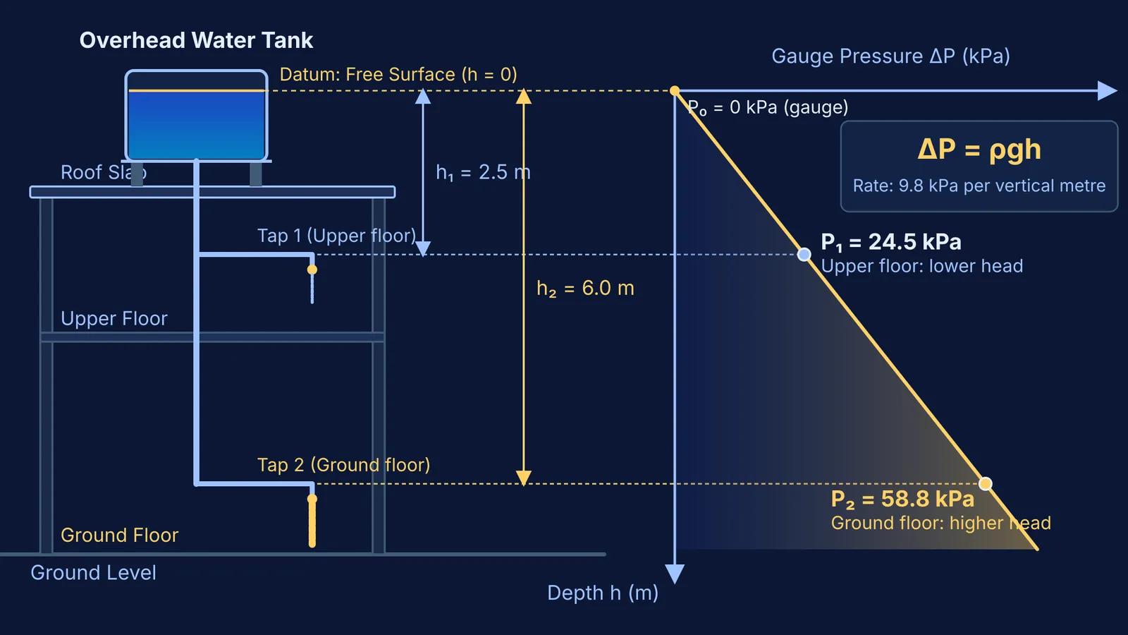
Consider a typical two-storey home where a 1,000-litre overhead water tank is mounted on a 1.5-metre masonry pedestal on the roof slab. Let us calculate the available static gauge pressure at two distinct fixtures using standard water density (1,000 kilograms per cubic metre) and acceleration due to gravity (9.8 metres per second squared), supported by OpenStax University Physics Volume 1:
First-floor bathroom shower: Located 2.5 metres below the water line in the tank. The static gauge pressure is ΔP₁ = (1000 kg/m³) × (9.8 m/s²) × (2.5 m) = 24,500 pascals (24.5 kilopascals, or 0.245 bar). This exceeds the 18 kilopascal minimum residual head required by IS 2065:1983.
Ground-floor kitchen tap: Located 6.0 metres below the water line. The static gauge pressure is ΔP₂ = (1000 kg/m³) × (9.8 m/s²) × (6.0 m) = 58,800 pascals (58.8 kilopascals, or 0.588 bar).
Once a tap opens and water begins to flow, the dynamic pressure delivered to the fixture decreases slightly due to internal pipe wall friction and viscous dissipation. As established in the historical work of Daniel Bernoulli and fluid dynamics, fluid energy trades off between static pressure and kinetic velocity along a streamline. However, because static head establishes the baseline driving potential, elevating the source ensures adequate residual delivery even during peak household usage.
What happens when a rooftop tank lacks enough vertical head?
When the elevation gap between the tank and the highest fixture is insufficient, everyday fixtures fail to operate smoothly. Modern appliances like automatic washing machines, wall-hung flush valves, and instant gas geysers require reliable terminal pressure. Under IS 2065:1983, standard flush valves demand a minimum working head of 0.10 newtons per square millimetre (approximately 10 metres of head, or 100 kilopascals), far exceeding the 1 to 2 metres available directly beneath a standard roof slab.
Plumbers solve this deficiency using three primary engineering strategies:
Elevating the tank platform: Raising the tank on a 3-metre to 4-metre steel staging frame increases h across the entire floor layout.
Installing an in-line booster pump: Dedicated automatic pressure-boosting pumps activate only when top-floor taps open, restoring flow without pressurising the entire building network.
Multi-zone piping: In multi-storey apartments, downcomers from rooftop tanks serve upper floors while pressure-reducing valves throttle flow to lower floors, keeping static pressure below structural piping limits.
Visualising fluid mechanics with interactive tools
Connecting classroom fluid formulas to real-world plumbing transforms how students develop practical intuition for fluid statics. When learning fluid mechanics, textbook diagrams often present static cross-sections that make it hard to picture how pressure fields shift when fluids move through bends, constrictions, and open orifices. In the Fermi Simulation Lab, students can explore interactive simulations for ideas that are easier to see than to read, manipulating fluid column heights, tank cross-sections, and discharge depths in real time. The Fermi Problem Library pairs theory with worked problems through a step-by-step solver that explains the reasoning rather than printing an answer, helping learners master fluid statics from first principles.


