

On this page
When you turn on a ceiling fan in an Indian home, single-phase alternating current enters the motor at 230 V and 50 Hz. Unlike three-phase industrial motors that produce a rotating magnetic field from three separate lines, a single-phase supply feeds a sinusoidal wave into a stationary coil. This current generates an alternating magnetic field along a single axis. The field oscillates, but it never rotates.
Why cannot a single-phase AC motor start on its own?
In 1888, the Italian physicist Galileo Ferraris demonstrated the physics of rotating magnetic fields produced by alternating currents in his landmark paper in *Il Nuovo Cimento*. In single-phase motors, double revolving field theory shows that any single-phase pulsating magnetic field resolves mathematically into two equal fields rotating in opposite directions at synchronous speed.
At rest, the stationary rotor has a slip of exactly 1 for both the forward and backward fields. Because both counter-rotating fields cut the rotor at identical speeds, their induced torques are equal and opposite. The net starting torque is zero. The motor hums at 100 Hz—twice the 50 Hz line frequency—vibrating without turning, a vector cancellation explored in our guide to AC circuits and phasors.
How does a capacitor split the AC phase to create torque?
To create starting torque, the motor must produce a rotating magnetic field. This requires two conditions:
Two stator windings displaced in space by 90 electrical degrees.
Two alternating currents displaced in time phase by 90 degrees.
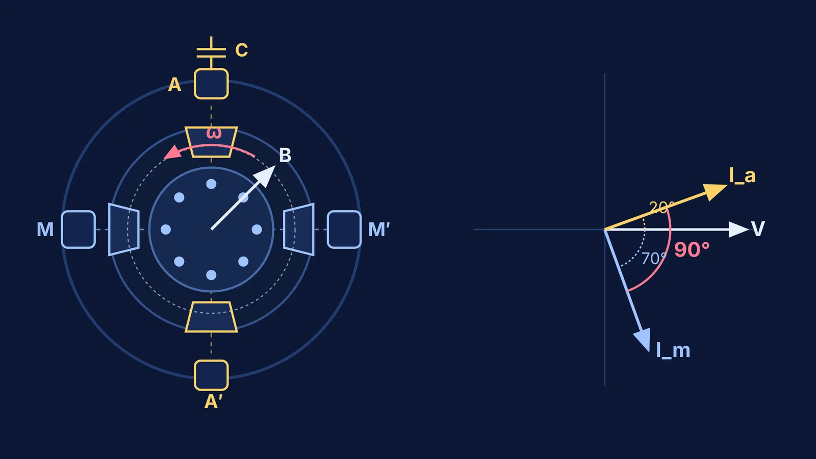
Ceiling fans use two copper coils: a main running winding and an auxiliary starting winding, wired in parallel across the 230 V supply. A capacitor is placed in series with the auxiliary winding. As detailed in the NCERT Class 12 Physics textbook, inductive current lags voltage, while capacitive current leads voltage by 90 degrees.
The main winding's inductance makes its current lag the supply voltage. In the auxiliary branch, the capacitor's reactance pulls current into a leading phase, creating an overall phase difference near 90 degrees. The two orthogonal fluxes combine into a single vector of steady magnitude that sweeps around the stator, dragging the rotor along.
Under Bureau of Indian Standards specification IS 374:2019 on Internet Archive, ceiling fans use a permanent-split capacitor design that keeps the capacitor connected during operation. This ensures quiet running and maintains an operating power factor of at least 0.90.
The Fermi Simulation Lab provides interactive simulations for ideas that are easier to see than to read, letting students adjust phase angles and observe how the resultant magnetic field vector rotates in real time.
What happens when a ceiling fan capacitor degrades or fails?
Over years of seasonal heat, the dielectric film inside the capacitor degrades. Most fan capacitors are self-healing metallized polypropylene units certified under Indian Standards such as IS 374:2019. When micro-breakdowns occur, the metallized layer vaporizes to isolate flaws, gradually reducing overall capacitance.
A capacitor rated at 2.25 µF or 2.5 µF can drop below 1.0 µF. As capacitance falls, its reactance climbs, choking auxiliary current and collapsing the phase shift. Starting torque disappears. If you nudge the blade with a ruler, the fan starts spinning because initial rotation reduces forward slip, allowing forward torque to dominate.
This degradation connects directly to core concepts in capacitors and dielectrics and reactive power in AC power and RMS values.
How do you calculate capacitive reactance and test a slow fan?
To calculate the impedance, consider a standard fan with a 2.5 µF capacitor on a 50 Hz supply. Using the reactance formula from the NCERT Class 12 Physics textbook:
XC = 1 / (2π f C) = 1 / (2 × 3.1416 × 50 s⁻¹ × 2.5 × 10⁻⁶ F) ≈ 1273 Ω.
On a 230 V supply, this reactance restricts auxiliary current to roughly 0.18 A, balancing startup torque against continuous thermal safety.
When troubleshooting a slow fan, follow this four-step diagnostic plan:
Check mechanical free-spin: Turn off power at the mains and spin the blades by hand. If rotation grinds or stops abruptly, the ball bearings are worn.
Isolate the electrical symptom: Switch power on. If the motor hums motionless but spins normally after a manual nudge, the auxiliary phase-split has failed.
Check the rated capacitance: Read the capacitor label on the motor housing. Under IS 374:2019, standard 1200 mm fans specify 2.25 µF or 2.5 µF, rated at 400 V or 440 V AC.
Test with a multimeter: Disconnect the capacitor and discharge its terminals safely. Measure capacitance with a digital meter; if it reads over 10% below its rating, replace it with an exact match.
When working through AC circuit problems, the Fermi Problem Library provides worked problems with a step-by-step solver that explains the reasoning rather than printing an answer.


