

On this page
In optics, seeing the actual path of a light beam is difficult because light travels invisibly. The pin experiment solves this by using physical markers to track the straight lines light follows. By carefully sighting the reflection of optical pins in a mirror, you can map exact light rays on a piece of paper.
What are the laws of reflection?
Before touching the drawing board, you must understand the rules you are trying to prove. According to Wikipedia), reflection is governed by two laws:
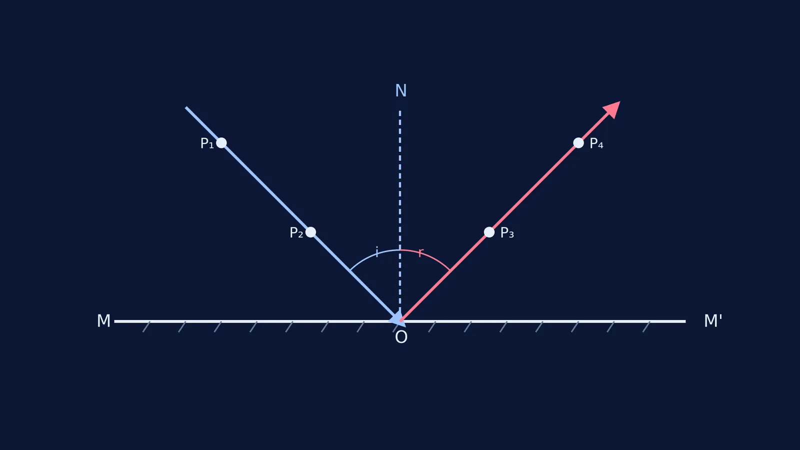
The angle of incidence is equal to the angle of reflection. Both angles are measured from the normal—an imaginary perpendicular line drawn at the point where light hits the mirror. If a light ray strikes the mirror at 40° to the normal, it will bounce off at exactly 40° on the opposite side.
The incident ray, the reflected ray, and the normal at the point of incidence all lie in the same plane. Because you plot the incoming ray, the normal, and the outgoing ray flat on a single sheet of paper, you naturally verify this rule.
How do you set up the laws of reflection experiment with pins and plane mirror?
Setting up the experiment requires a drawing board, a white sheet of paper, a thin plane mirror with a vertical stand, drawing pins, and four optical pins.
Here is the standard procedure:
Fasten the white paper flat onto the drawing board.
Draw a straight horizontal line MM' across the center. This marks where the back silvered edge of the mirror will sit.
Mark a point O near the center of the MM' line. Use a protractor to draw a dashed line ON perpendicular (at 90°) to MM' originating from O. This is your normal.
Draw an incident ray line, PO, coming into O at a specific angle.
Push two optical pins (P₁ and P₂) vertically along the PO line.
Place the plane mirror upright on MM', ensuring its reflecting surface faces the pins.
Lower your eye level on the opposite side of the normal. Look into the mirror to find the virtual images of P₁ and P₂.
Stick a third pin (P₃) into the paper so that it perfectly hides the reflected images of the first two pins.
Do the same with a fourth pin (P₄), creating a single visual line with P₃ and the reflections.
If the underlying geometry feels overwhelming, the Fermi Problem Library offers worked problems with a step-by-step solver that explains the reasoning rather than printing an answer.
How do you measure the angles of incidence and reflection?
Once all four pins are aligned, the physical portion is done. Remove the mirror and pull out the pins. Immediately circle the small holes left by P₃ and P₄ with a pencil.
Use a ruler to draw a straight line through P₃ and P₄, extending it to point O. This new line is your reflected ray. You now have a physical record of the light's path, a technique similarly used when tracing a ray through a glass slab.
To analyze the results, place the baseline of your protractor on the normal line ON, with its center on O. Read the angle between the normal and your incident ray to record your angle of incidence (i). Then, measure the angle between the normal and your newly drawn reflected ray to find your angle of reflection (r). For a successful experiment, these two numbers will be identical.
What precautions should you take in this experiment?
Standard optical experiment procedures highlight a few critical precautions to ensure accurate data:
Use a thin glass mirror: Thick glass creates a secondary reflection from the front surface before the main reflection off the silvered back. This makes it difficult to align your pins.
Keep the pins strictly vertical: If your pins are slanted, their bases will not align with their heads. This creates parallax errors when sighting them from a low angle.
Space the pins appropriately: Placing pins widely apart provides a longer baseline, making it much easier to sight a perfectly straight optical line.
By mastering this precise setup, you can move on to more advanced optical phenomena, such as determining what happens when rotating a plane mirror by θ. If you find it difficult to picture how these rays move dynamically, the Fermi Simulation Lab provides interactive simulations for the ideas that are easier to see than to read.


