

On this page
When you flip a wall switch, a lamp turns on instantly; flip it back, and the light vanishes. In school science, this everyday action illustrates the fundamental difference between an open and a closed electric circuit.
According to the NCERT Class 6 Science curriculum, an electric circuit provides a complete pathway for electricity to travel between the terminals of an electric cell. Mastering how this loop opens and closes is the foundation of all circuit physics.
What is the difference between an open circuit and a closed circuit?
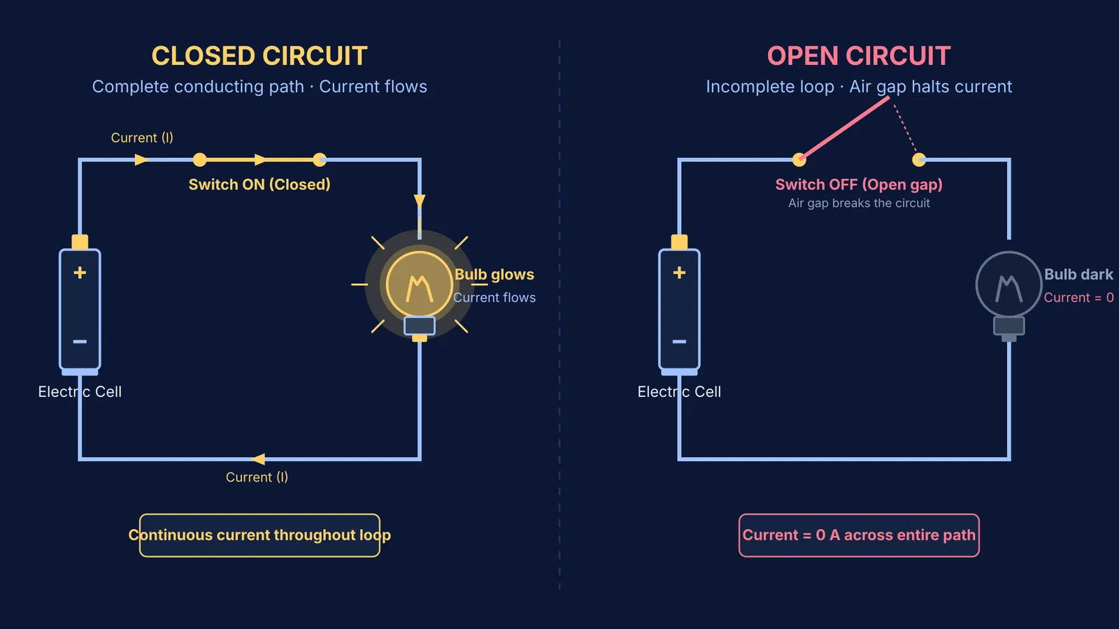
The difference between an open circuit and a closed circuit centres on path continuity.
A closed circuit is an unbroken conducting loop running from the positive terminal of a cell, through connecting wires and an electrical load such as a bulb, and back to the negative terminal. Because the loop contains no gaps, electric charges circulate continuously. Current flows from the positive terminal to the negative terminal through the external wiring, heating the bulb's filament until it glows.
An open circuit contains a physical gap or discontinuity at some point in the conducting path. That break can be an open switch, a loose connection, a disconnected wire, or a broken filament inside a bulb. Because electric charges cannot jump across an air gap at ordinary voltages, current stops throughout the entire loop. In an open circuit, current is zero everywhere, and the bulb stays dark.
Why does current require an unbroken loop?
Many middle-school learners initially picture electricity as a fluid that pours out of a single wire into a bulb and gets consumed.
Physics education research shows this misconception persists well beyond school. In a study published in The Physics Teacher, researchers Norman Fredette and John Lochhead asked freshman engineering students to light a bulb using only one wire and a single cell. Roughly one-third of the students failed because they held a "sink model," believing current travels along one wire without needing a return path. Research by Lillian C. McDermott and Peter S. Shaffer in the American Journal of Physics similarly found that students assume current flows up to an open switch and stops.
In reality, mobile electrons already fill every metal wire and filament. The cell provides an electric potential difference that drives these charges simultaneously around the entire loop. If the path opens anywhere, the driving field collapses and circulating current drops to zero.
The Fermi Concept Library maps every concept in physics, chemistry, biology, mathematics and computing, each with its own lesson and its place in the map. To see these invisible charges in motion, the Fermi Simulation Lab offers interactive simulations for ideas that are easier to see than to read.
How does a switch open and close an electric circuit?
A switch is a simple control mechanism designed to open or close an electric circuit without disconnecting wires manually:
Closed position (ON): The switch presses metal contacts together, completing the conducting loop so current flows freely.
Open position (OFF): The switch separates the metal contacts, introducing a layer of air. Because dry air is an insulator, it breaks the conducting loop and stops all current.
A fused bulb acts exactly like an open switch. Inside an incandescent bulb, a thin coiled filament connects two support wires attached to the casing and bottom tip. If this filament snaps from excess current or age, it creates an internal air gap that permanently opens the circuit, even when all external wires remain attached.
To see how these single-loop circuits expand into more complex networks, explore Class 7 electricity: how to tell if a circuit will work and Electricity in Class 10: Ohm's law, resistors and electric power.
How can you test whether a circuit is complete?
When a circuit fails during a science activity, use this four-step diagnostic checklist to find where the path is open:
Trace the physical loop: Follow the wire from the cell's positive cap through every component back to the flat negative disc. If the metal path breaks anywhere, the circuit is open.
Check bulb contact points: A bulb requires two separate contact points. One wire must touch the side metal casing, and the other must touch the metal tip at the base. Touching both wires to the casing leaves the filament disconnected.
Inspect switch contacts: Ensure metal contacts touch firmly without dirt, tape, or corrosion acting as unintended insulation.
Test material conductivity: Verify that all bridging materials are electrical conductors (like copper, aluminium, or iron) rather than insulators (like plastic or wood).
Practising this checklist builds experimental intuition and eliminates guesswork during exams. You can also explore Learning DC circuits with a simulation to test different wiring faults virtually. When facing tricky circuit questions, the Fermi Problem Library provides worked problems with a step-by-step solver that explains the reasoning rather than printing an answer.


