

On this page
A standard compound microscope is the centrepiece of any high school biology laboratory. Whether you are observing a cross-section of a dicot stem or counting the stages of mitosis in an onion root tip, understanding its parts and how they work together is essential. In practical exams, drawing a neatly labelled diagram of the microscope is often the first step to securing full marks.
Let us walk through the optical and mechanical parts of a compound microscope, what each component does, and the standard way to label them for your records.
What are the optical parts of a compound microscope?
The optical system is responsible for illuminating the specimen and magnifying its image.
Eyepiece (Ocular Lens): This is the lens you look through at the top of the microscope. Common eyepiece magnifications include 5×, 10× (which is the most common), 15×, and 20× (Wikipedia).
Objective Lenses: Located on a rotating nosepiece just above the specimen, these are the primary lenses that do the heavy lifting of magnification. They typically range from 5× to 100× (Wikipedia).
Condenser: Sitting below the stage, the condenser is a lens system that gathers light from the source and focuses it into a concentrated beam onto the specimen.
Iris Diaphragm: Found just under the condenser, the diaphragm controls the amount of light reaching the slide. Adjusting the diaphragm improves contrast and clarity; too much light washes out the details, while too little makes the image impossibly dark.
When these lenses work together, they are subject to the laws of physics. The maximum resolving power of standard optical microscopes is typically limited to around 200 nanometers (Wikipedia) due to the diffraction limit of visible light. (If you want to read about the physicist who defined this boundary, see Ernst Abbe and the numerical aperture of the microscope).
What are the mechanical parts of a compound microscope?
The mechanical parts provide the structural framework, keeping the delicate optics perfectly aligned while allowing you to focus precisely.
Base and Arm: The heavy base gives the microscope stability on the workbench, while the curved arm provides a rigid support for the optical tube and a safe place to grip when carrying the instrument.
Stage: This is the flat platform where you place your glass slide. It has a central hole (the aperture) to let light through, and usually features stage clips or a mechanical mechanism to hold the slide steady.
Coarse Adjustment Knob: This large knob moves the stage up and down in significant increments. It is used only with the lowest-power objective to bring the specimen into the general field of view.
Fine Adjustment Knob: Once the specimen is roughly in view, this smaller knob moves the stage in tiny, precise steps to bring the image into razor-sharp focus. Never use the coarse adjustment with a high-power objective, as you risk cracking the slide against the lens.
How do you calculate total magnification?
The compound microscope is named for its two-stage magnification process. The objective lens forms a real, inverted and magnified intermediate image of the object. The eyepiece then acts as a simple magnifier, enlarging this intermediate image into a final virtual image. (For a detailed mathematical look at this two-stage process, see our guide on the Magnifying power of microscopes and telescopes).
To find the total magnification, you simply multiply the power of the eyepiece by the power of the objective lens you are using. For example, if you are looking through a 10× eyepiece and have selected a 40× objective lens, the total magnification is 10 × 40 = 400×.
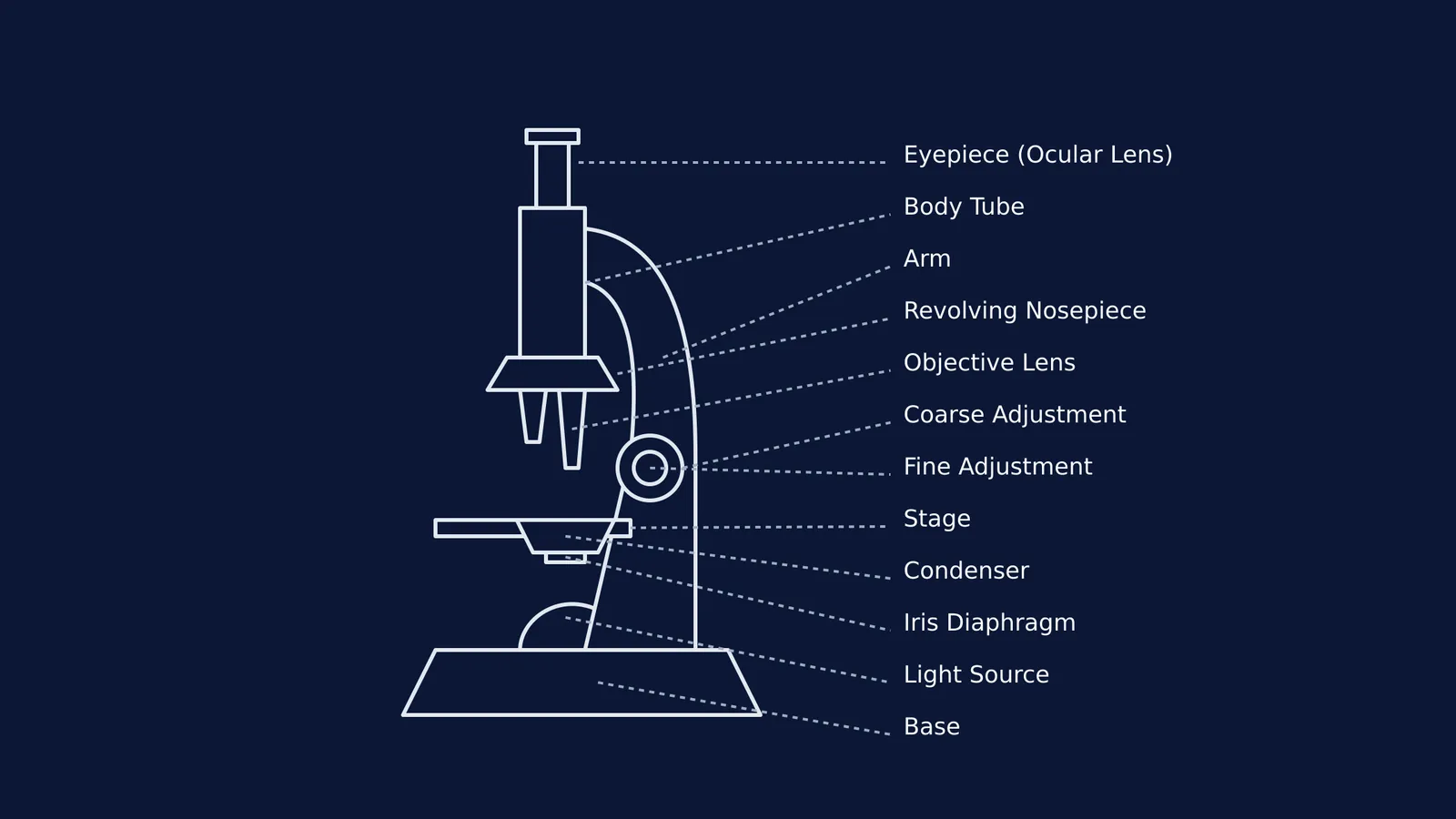
How to draw and label a microscope diagram for practical files?
Drawing a clean, accurate diagram is a core skill for biology practical files. Here is a checklist to ensure your diagram meets examiner expectations:
Use a sharp pencil: Always draw in pencil, never in pen, to allow for clean corrections.
Proportion over artistry: You do not need to shade or draw in 3D. A clean 2D side-profile outline is standard. Ensure the base is large and flat, and the arm correctly supports the body tube.
Right-aligned labels: Draw straight, horizontal label lines using a ruler. Keep all the text on the right-hand side of the diagram so it is easy to read.
Essential labels: At a minimum, your diagram must clearly label the Eyepiece, Body Tube, Coarse Adjustment, Fine Adjustment, Arm, Revolving Nosepiece, Objective Lens, Stage, Condenser, Diaphragm, Light Source (or Mirror), and Base.
When mastering concepts for your practicals, an active approach to learning builds the strongest foundation. The Fermi Concept Library has every concept in biology, physics and chemistry, each with its own lesson and its place in the map. It offers a structured way to engage with the material directly, moving beyond passive reading into active problem-solving.


