

On this page
When a radio antenna intercepts electromagnetic waves, it picks up signals from dozens of broadcasting stations simultaneously. To listen to a single broadcast, the radio receiver must isolate one specific signal and reject all others. Inside the receiver, a series LCR—inductor, capacitor, and resistor—circuit acts as a highly selective band-pass filter to achieve this isolation.
Resonance in an LCR circuit occurs when the energy oscillates continuously between the electric field of the capacitor and the magnetic field of the inductor. This is often compared to a mechanical weight bouncing on a spring, where the electrical resistance acts like friction that eventually damps the oscillation.
By adjusting a variable component, usually the capacitor, you change the circuit's natural resonant frequency (f₀ = 1 / (2π√(LC))). Resonance occurs when this internal frequency perfectly matches the incoming frequency of the desired radio station. At this precise point, the inductive reactance and capacitive reactance cancel each other out (X_L = X_C). Because they are equal in magnitude but opposite in sign, the circuit's impedance drops to its absolute minimum, becoming purely resistive. With impedance minimized, the current for that specific station reaches its maximum value (I = V/R), allowing the signal to pass through the filter strongly.
In older analog radios, tuning was physically done by turning a dial that moved the interlocking plates of a variable capacitor, changing the effective area and therefore the capacitance. In other stages of a radio receiver, such as the Intermediate Frequency (IF) stage, tuning is instead preset at the factory using an adjustable inductor core made of high-permeability material. Turning the threaded core inwards or outwards changes the inductance. Either way, changing L or C shifts the resonance peak to exactly the desired frequency.
What gives a radio high selectivity?
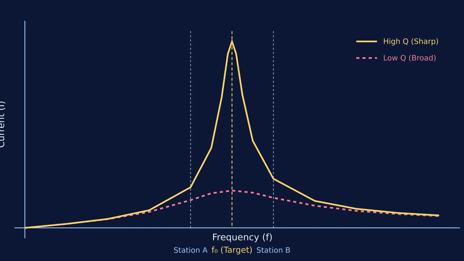
Selectivity is a circuit's ability to distinguish between the desired signal and other nearby frequencies. If you tune into a news station, you do not want to hear a faint, distorted music broadcast from an adjacent channel playing over it. Selectivity depends entirely on the "sharpness" of the resonance curve, which is defined by a dimensionless parameter called the Quality factor, or Q-factor.
The Q-factor characterizes the efficiency of the resonator by comparing the peak energy stored in the circuit to the average energy lost to resistance during each cycle. For a series circuit, Q = (1/R)√(L/C). A highly selective circuit has a low resistance (R), resulting in a high Q-factor and a narrow bandwidth. This sharp peak ensures that while the tuned station's current is amplified, the signals from adjacent stations—which are slightly off-resonance—encounter very high impedance and remain negligible.
Conversely, a broad, low-Q curve would let multiple stations through, causing them to interfere with each other. If the resistance in the tuning circuit is too high, the damping flattens the peak, completely ruining the selectivity.
How do bandwidth and damping interact?
To understand tuning fully, you must look at bandwidth (Δf). This is the range of frequencies over which the power in the circuit is at least half of its peak value at resonance. Bandwidth is inversely related to the Q-factor: Q = f₀ / Δf.
A narrow-band filter requires low damping (high Q), which is exactly what a radio tuner needs. But there is a practical trade-off in circuit design. If a circuit has an extremely high Q-factor, it becomes prone to "ringing," which means it continues to oscillate on its own after the original source signal stops. The radio engineer must design the LCR circuit with just enough resistance to prevent unwanted ringing, but not so much that the bandwidth widens and lets neighboring stations bleed through. This balance is critical for the clear reception of a single radio frequency without distortion.
Besides selecting stations, LCR circuits are used as band-stop (or notch) filters to eliminate specific interfering frequencies, and as oscillators to generate carrier waves for radio transmitters. In oscillators, resistance is kept as close to zero as possible to maintain a very high Q-factor and a perfectly stable oscillation.
How do students learn resonance?
A 2016 paper in *Physics Education* (10.1088/0031-9120/51/6/065006) showed how using simple circuitry attached to a microcontroller allows learners to display and investigate characteristic resonance curves for a series LCR circuit dynamically.
If you find it difficult to picture why changing a capacitor alters the current, the Fermi Concept Library can help. Rather than just giving you the formula, Fermi's AI tutor builds a plan for your session, running the simulation and drawing the resonance curve as you adjust the capacitance to see the station fade in and out.
For more on alternating signals and waves, read about the energy density and intensity of an EM wave, or see how to apply the node potential method to complex networks.


