

On this page
When you tune an alternating current (AC) circuit, its behaviour changes drastically depending on the frequency of the source. The classic series LCR circuit—made of an inductor (L), a capacitor (C) and a resistor (R)—can act like three completely different circuits as you turn the frequency dial.
So, what happens to the circuit before it hits its resonant frequency?
Is an LCR circuit inductive or capacitive below resonance?
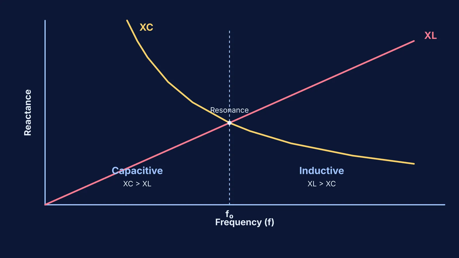
Below its resonant frequency (f₀), a series LCR circuit is primarily capacitive.
According to the official NCERT Class 12 Physics textbook, in a series LCR circuit below resonance, the capacitive reactance (X_C) is greater than the inductive reactance (X_L). Because the capacitor dominates the total opposition to the current, the overall circuit behaves much like a simple RC circuit. The net reactance is capacitive, and as a result, the alternating current leads the applied voltage.
Why does the capacitor dominate at low frequencies?
To see why the circuit changes character, look at how the two reactances depend on the angular frequency (ω = 2πf):
Inductive reactance is X_L = ωL. It grows linearly with frequency. At low frequencies, the inductor offers very little opposition to the current.
Capacitive reactance is X_C = 1/(ωC). It is inversely proportional to frequency. At low frequencies, the capacitor puts up a huge resistance to the flow of current.
Because they are in series, the larger reactance wins. At frequencies below f₀, the massive X_C dwarfs the tiny X_L. The difference between them (X_C − X_L) dictates the circuit's phase angle, driving the current to lead the voltage. This is a common stumbling block in entrance exams; if you need to build a mental map of how these components behave individually over time, try our guide on inductors at t = 0 and t = ∞.
What happens when the frequency goes above resonance?
As you dial the frequency past f₀, the tables turn.
The inductive reactance (X_L) keeps climbing, while the capacitive reactance (X_C) shrinks away toward zero. Above resonance, X_L is much greater than X_C. The inductor now dominates the circuit, making it inductive overall. The current starts to lag the voltage, just as it would in an RL circuit.
At exactly the resonant frequency (f₀ = 1 / (2π√(LC))), the two reactances are perfectly equal. They cancel each other out entirely (X_L = X_C), leaving only the resistor R to oppose the current. This is why the circuit is purely resistive at resonance.
How do you spot this in a JEE or NEET problem?
Examiners love to test this concept without explicitly stating the frequency. They might give you a circuit where a 10 μF capacitor and a 10 mH inductor are connected to an AC source of 50 Hz.
First, find the resonant frequency: f₀ = 1 / (2π√(LC)).
For C = 10⁻⁵ F and L = 10⁻² H, the product LC is 10⁻⁷.
This makes f₀ ≈ 503 Hz.
Since the applied 50 Hz is well below 503 Hz, you instantly know the circuit is capacitive and the current will lead the voltage. You can apply this same logic to inserting a dielectric slab problems or when using the node potential method for more complex AC networks.
If you find yourself mixing up phase angles and reactances, you can explore the underlying rules step by step in the Fermi Concept Library. Our AI tutor will help you derive the phasor diagram from scratch so you never have to memorise the phase relationship again.


