

On this page
Finding the magnetic field near an L-shaped current-carrying wire is a classic test of superposition. Instead of setting up a complex integral from scratch, you can break the "L" into two semi-infinite straight wires and add their magnetic fields together.
This superposition method is a standard trick in electromagnetism, much like adding the individual potentials of concentric spherical shells to find the total voltage. If you know the field of one straight segment, you can find the field of the bent wire.
What is the formula for a straight wire segment?
Using the Biot-Savart law, the magnetic field B at a perpendicular distance R from a finite straight wire segment can be calculated by integrating along the wire. A standard result of this integration is the formula B = (μ₀I / 4πR)(sin θ₂ − sin θ₁).
Here, θ₁ and θ₂ are the angles measured from the perpendicular to the two ends of the wire. If an end is to the left of the perpendicular, its angle is negative; if it is to the right, it is positive. For a semi-infinite wire that starts at a point and extends to infinity, one of these angles will be 90°.
How do you find the field on the bisector inside the bend?
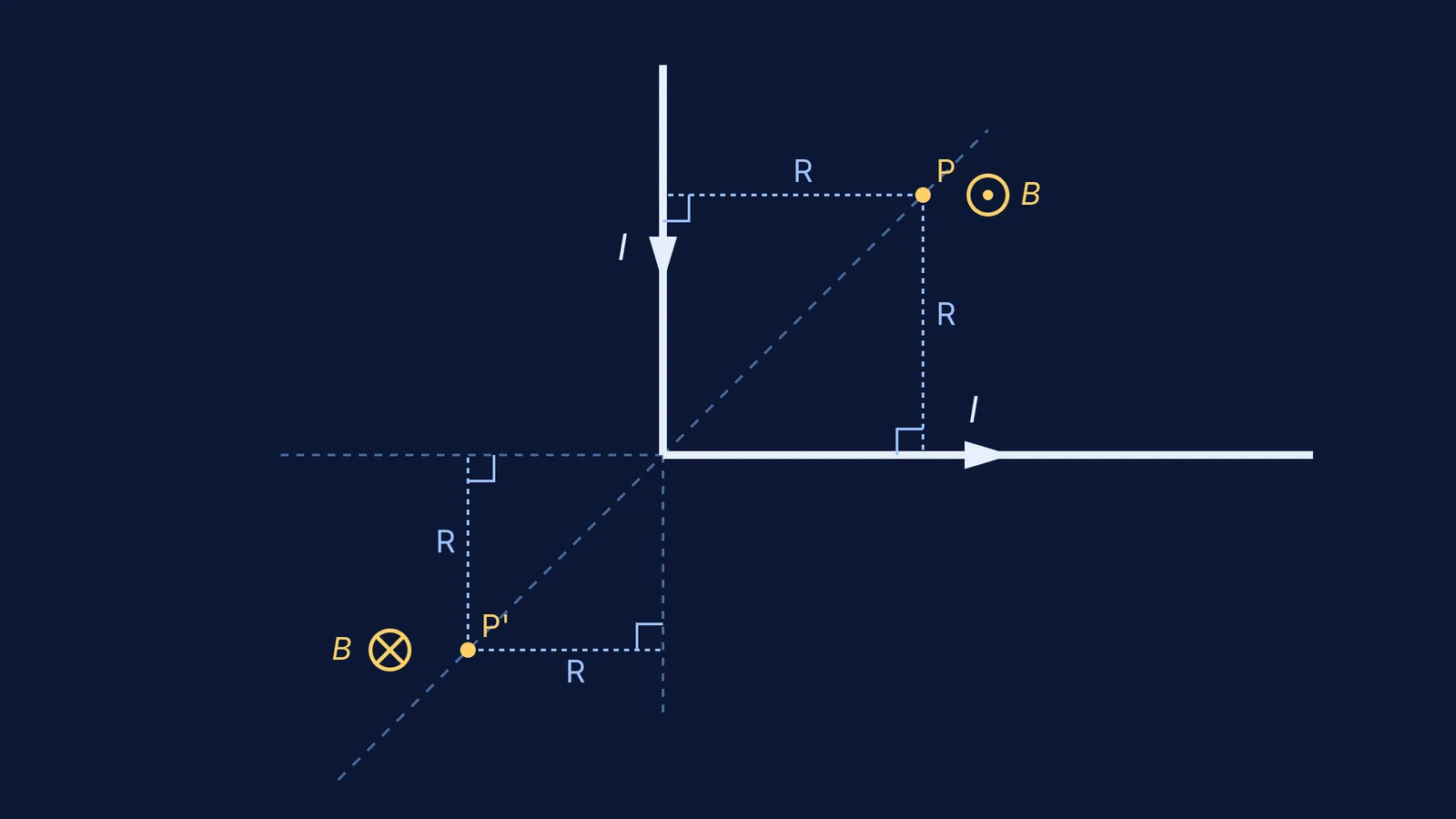
Imagine an L-shaped wire carrying a current I that flows down the y-axis to the origin, and then turns to flow along the positive x-axis to infinity. Let's find the magnetic field at a point P on the angle bisector "inside" the bend, at a distance r from the corner.
Because P is on the bisector, its coordinates are (r/√2, r/√2). The perpendicular distance R to each arm is r/√2.
The x-axis arm: The perpendicular from P drops at x = r/√2. The wire starts at the origin (x = 0), which is to the left of the perpendicular, so θ₁ = −45°. It extends to infinity, so θ₂ = 90°.
Using the formula, the field is B_x = [μ₀I / 4π(r/√2)] × (sin 90° − sin(−45°)) = [μ₀I / 4π(r/√2)] × (1 + 1/√2).
The y-axis arm: By symmetry, this arm produces the exact same magnitude of magnetic field.
The vector sum: Using the right-hand rule, both arms produce a magnetic field that points completely out of the page at point P.
Because they point in the same direction, we just add them: B_inside = 2 × [μ₀I√2 / 4πr] × (1 + 1/√2) = (μ₀I / 2πr)(√2 + 1)
If you are practicing for an exam, drawing the angles is where most mistakes happen, much like dropping a negative sign when calculating the work to assemble point charges. If you get stuck visualising the geometry, the Fermi Concept Library has a full lesson on the Biot-Savart law, and Fermi's AI tutor can draw the figure with you and walk you through the angle assignments step by step.
What is the field on the bisector outside the bend?
Now pick a point P' on the bisector but "outside" the L, at a distance r from the corner (in the third quadrant). The perpendicular distance to the line of each arm is still R = r/√2.
However, the geometry of the angles changes:
The perpendicular from P' to the x-axis drops at x = −r/√2.
The wire itself only starts at x = 0, which is now to the *right* of the perpendicular.
This means θ₁ = +45°. The wire still extends to infinity (θ₂ = 90°).
The field from the x-axis arm is now B_x = [μ₀I / 4π(r/√2)] × (sin 90° − sin 45°) = [μ₀I√2 / 4πr] × (1 − 1/√2).
Again, by the right-hand rule, both arms produce fields that point in the same direction (this time, into the page). Adding both contributions gives: B_outside = 2 × [μ₀I√2 / 4πr] × (1 − 1/√2) = (μ₀I / 2πr)(√2 − 1)
Notice how shifting the point outside the bend turns the (1 + 1/√2) term into a subtraction.
How do you find the field along the axis of an arm?
What if the point is on the exact line of one of the wires, but outside the bend? For example, a point on the negative x-axis at a distance r from the origin.
The x-axis arm: Because the point lies exactly on the line of this current, the angle between the current and the position vector is zero. The Biot-Savart law says this arm produces zero magnetic field at that point.
The y-axis arm: The perpendicular from the point to the y-axis drops exactly at the origin. The wire starts at the origin (θ₁ = 0°) and goes to infinity (θ₂ = 90°).
The field is entirely due to the y-axis arm: B_axis = (μ₀I / 4πr)(sin 90° − sin 0°) = μ₀I / 4πr
This is exactly half the magnetic field of an infinitely long wire, which makes sense because you are looking at exactly half of an infinite wire. If you want to explore how these fields change dynamically, you can build this setup in the Fermi Simulation Lab and drag the test point around the wire to watch the vectors stretch and flip.


