

On this page
In a circuit, inductors behave much like resistors as long as they are magnetically shielded or far enough apart that their magnetic fields do not overlap. The equivalent inductance tells you the total opposition to changes in current provided by the network [[1]](https://en.wikipedia.org/wiki/Inductance).
Why do inductors add like resistors?
For inductors in series, the same current flows through all the components. The total induced back-EMF (voltage) is just the sum of the individual voltages across each coil. Therefore, their inductances add up directly [[1]](https://en.wikipedia.org/wiki/Inductance):
L_eq = L₁ + L₂ + L₃ + ...
For inductors in parallel, the voltage across each inductor is the same, but current splits among the branches. Equivalent inductance drops, following the reciprocal rule used for parallel resistors [[1]](https://en.wikipedia.org/wiki/Inductance):
1/L_eq = 1/L₁ + 1/L₂ + 1/L₃ + ...
For exactly two inductors in parallel, this simplifies to the familiar product-over-sum formula: L_eq = (L₁ × L₂) / (L₁ + L₂).
When using the Fermi Problem Library for AC circuits, you will often spot these idealised components. Without mutual inductance, replacing a block of inductors with a single equivalent value follows the exact same algebra as finding the equivalent resistance of an infinite ladder.
How does mutual inductance change the rules?
The basic resistor rules break down when inductors are close enough to share magnetic flux. When a changing current in one coil induces a voltage in the other, they are coupled by a mutual inductance, M [[1]](https://en.wikipedia.org/wiki/Inductance).
Because the coils are now linked, the voltage across each inductor depends on the current changing in *both* coils. This introduces extra terms into the equivalent inductance formulas. To solve these, you need to know whether the magnetic fields created by the two coils are pushing in the same direction or fighting each other [[2]](https://en.wikipedia.org/wiki/Dot_convention).
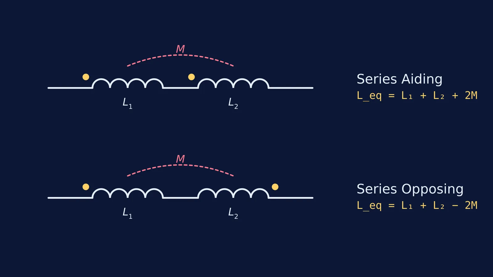
Circuit diagrams use a "dot convention" to show this [[2]](https://en.wikipedia.org/wiki/Dot_convention). If the current enters the dotted terminals of both coils, their fields are aiding (reinforcing each other). If it enters the dotted terminal of one but the undotted terminal of the other, their fields are opposing (cancelling each other out) [[2]](https://en.wikipedia.org/wiki/Dot_convention).
What is the equivalent inductance with mutual coupling?
For two coupled inductors L₁ and L₂ sharing a mutual inductance M, the formulas adjust to include the flux linkage [[1]](https://en.wikipedia.org/wiki/Inductance).
Coupled Inductors in Series In series, the same current passes through both coils. The induced voltage from the mutual inductance either adds to or subtracts from the self-induced voltage of the coils [[1]](https://en.wikipedia.org/wiki/Inductance):
Series Aiding: L_eq = L₁ + L₂ + 2M
Series Opposing: L_eq = L₁ + L₂ − 2M
Coupled Inductors in Parallel In parallel, the current divides, making the math more complex because the induced voltages must still match across the parallel branches. The resulting equivalent inductance depends heavily on the dot placement [[1]](https://en.wikipedia.org/wiki/Inductance):
Parallel Aiding: L_eq = (L₁L₂ − M²) / (L₁ + L₂ − 2M)
Parallel Opposing: L_eq = (L₁L₂ − M²) / (L₁ + L₂ + 2M)
A worked example: How do series inductors behave on a shared core?
Let's look at how this plays out in a hypothetical physics problem. Suppose you have two coils wound on the same iron core. Coil 1 has a self-inductance of 4.0 H, and Coil 2 has a self-inductance of 6.0 H. Because they share a high-permeability core, they are tightly coupled with a mutual inductance of 3.0 H [[1]](https://en.wikipedia.org/wiki/Inductance).
How do you find the total equivalent inductance if they are connected in series?
Step 1: Check the connections (the dot convention) First, trace the wire. If the current flows from the positive terminal and enters the dotted end of Coil 1, and then follows the wire to enter the dotted end of Coil 2, the coils are in a series-aiding configuration [[2]](https://en.wikipedia.org/wiki/Dot_convention).
Step 2: Apply the series-aiding formula Since the magnetic fluxes point in the same direction, they reinforce each other. Use the aiding formula [[1]](https://en.wikipedia.org/wiki/Inductance): L_eq = L₁ + L₂ + 2M
Step 3: Calculate the total Plug in the values: L_eq = 4.0 + 6.0 + 2(3.0) L_eq = 10.0 + 6.0 = 16.0 H
If you reverse the connections on Coil 2, the fields will oppose each other [[2]](https://en.wikipedia.org/wiki/Dot_convention). The formula becomes L_eq = L₁ + L₂ − 2M, giving an equivalent inductance of 4.0 + 6.0 − 2(3.0) = 4.0 H.
Notice the huge difference the physical orientation makes: simply flipping two wires changes the circuit's total inductance from 16.0 H down to 4.0 H.
When should you use these formulas?
In most standard exam problems for JEE Main, JEE Advanced or NEET-UG, inductors are assumed to have zero mutual inductance unless a mutual inductance M or a coupling coefficient k is explicitly given. If you see a problem with dots on the coils or overlapping solenoids, that is your visual cue to bring in the 2M terms [[1]](https://en.wikipedia.org/wiki/Inductance). You can also apply similar careful analysis when dealing with complex circuits, such as inductors at t = 0 and t = ∞.
If you are unsure whether fields are aiding or opposing, try sketching the field lines using the right-hand grip rule. (You can also explore this visually in the Fermi Simulation Lab to see how overlapping fields reinforce or cancel in real time.) Tracing the direction of the current wrap-by-wrap will show you exactly how the dot convention translates to physical reality. To master the core ideas behind Faraday's and Lenz's laws, the Fermi Concept Library maps out how these magnetic interactions piece together.


