

On this page
Why do interference fringes form hyperbolas in 3D space?
Every introductory physics course begins Young's double-slit experiment by drawing two slits and sketching neat, alternating bright and dark stripes on a distant screen. Textbooks frequently call these stripes straight lines. Yet if you ask what shape the interference pattern takes in three dimensions, the answer changes entirely.
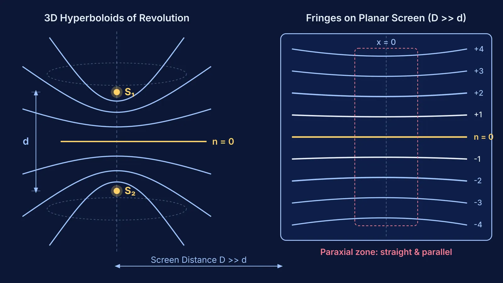
Interference depends on the optical path difference between waves arriving from two coherent point sources, S₁ and S₂. Constructive interference occurs whenever the path difference |S₁P − S₂P| equals an integer multiple of the wavelength, nλ, as detailed in NCERT Class 12 Physics. In pure coordinate geometry, the locus of all points whose distances to two fixed points differ by a constant value is a hyperbola.
Because light radiates in all directions, this condition does not apply only to a flat sheet of paper. Rotating that hyperbola around the axis passing through S₁ and S₂ sweeps out a three-dimensional surface called a confocal hyperboloid of two sheets. The two point sources act as the foci. In 3D space, every bright fringe is actually a hollow, nested hyperboloidal shell. Understanding this spatial wavefront geometry connects directly to converting phase difference to path difference across wave optics.
Why do fringes look like straight parallel lines on a screen?
What you see on a laboratory screen is simply a two-dimensional planar slice through these three-dimensional hyperboloidal shells. In the standard Young's arrangement, the screen is flat and placed parallel to the line connecting S₁ and S₂ at a distance D.
Analytic geometry shows that slicing a hyperboloid of revolution with a plane parallel to its axis yields a family of two-dimensional hyperbolas. If the sources lie along the vertical y-axis separated by distance d, the intersection on a screen at distance D follows the hyperbola equation y² / [a²(1 + D² / b²)] − x² / [b² + D²] = 1, where a = nλ / 2 and b² = (d / 2)² − (nλ / 2)².
Why then do the bands appear straight? The answer lies in the ratio between the slit separation d and the screen distance D. As established in NCERT Class 12 Physics, in a standard classroom setup, d is roughly 1.0 mm while D is 1.0 m, making D one thousand times larger than d. Near the optical axis where x is small, the hyperbola's vertex has an enormous radius of curvature, given by R = D² / y₀. Across a typical microscope field of view of 10 mm to 20 mm, the sagitta (the sideways bend) is less than 2 micrometres. Because this bow is less than 0.3% of the fringe width itself, human eyes and traveling microscopes perceive the central fringes as perfectly straight, parallel lines.
When visualizing how three-dimensional wave surfaces propagate and intersect in space, reading static two-dimensional diagrams can leave gaps in your physical intuition. The Fermi Simulation Lab provides interactive simulations for ideas that are easier to see than to read, allowing students to inspect wave surfaces from any viewing angle.
What happens when you change the screen's orientation?
Because fringes are intersections of three-dimensional shells with a two-dimensional surface, tilting or rotating the screen transforms the observed pattern into different conic sections:
Screen parallel to the source axis: Slicing parallel to the axis of revolution produces hyperbolas, which look like straight parallel lines near the center.
Screen perpendicular to the source axis: Placing the screen across the line joining S₁ and S₂ yields concentric circular rings, centered on the axis.
Screen tilted at an oblique angle: Depending on the angle between the cutting plane and the asymptote of the hyperboloid, the fringes become ellipses or parabolas.
A study by Joseph Ivin Thomas in the European Journal of Physics demonstrated that the total number of interference fringes in space is strictly bounded by Ω = 2⌊d / λ⌋ + 1, because the path difference cannot exceed the source separation d. Thomas also showed that fringe spacing is fundamentally non-uniform: fringes are packed most densely near the central axis and disperse outward toward the edges of a flat screen.
Historically, this wave behavior puzzled early natural philosophers until Grimaldi's first observation of diffraction bands proved that light bends around edges rather than traveling in strict geometric rays. In practical laboratory experiments, researchers use narrow slits rather than pinholes. A linear slit acts as a continuous line of coherent point sources. Integrating these individual hyperboloids along the length of parallel slits reinforces the central straight segments into bright, high-contrast bands, averaging out the faint lateral curvature.
For students exploring how medium properties change fringe patterns, understanding how wavelength shifts across media explains why immersing the entire setup in water compresses both the hyperboloids and the fringe spacing by the refractive index μ.
Worked example: calculating the curvature deviation
To see why the straight-line approximation holds so well near the centre, let us compute the exact sagitta of a fringe using typical laboratory parameters from NCERT Class 12 Physics:
Identify the experimental parameters:
Light wavelength: λ = 600 nm = 6.0 × 10⁻⁷ m
Slit separation: d = 1.0 mm = 1.0 × 10⁻³ m
Distance to screen: D = 1.0 m = 1000 mm
Calculate the central fringe position:
The fringe width is β = λD / d = (6.0 × 10⁻⁷ m × 1.0 m) / (1.0 × 10⁻³ m) = 0.6 mm = 600 μm.
For the 10th bright fringe (n = 10), the central position at x = 0 is y₀ = 10 × β = 6.0 mm.
Calculate the coordinate on the hyperbolic curve at x = 20 mm:
The hyperbola on the screen obeys y(x) = y₀ × √(1 + x² / D²).
For x = 20 mm and D = 1000 mm, the factor x² / D² is (20 / 1000)² = 4.0 × 10⁻⁴.
Using the binomial approximation, √(1 + 4.0 × 10⁻⁴) ≈ 1 + 2.0 × 10⁻⁴.
Therefore, y(20 mm) = 6.0 mm × (1 + 0.0002) = 6.0012 mm.
Evaluate the curvature:
The deviation is Δy = 6.0012 mm − 6.0000 mm = 0.0012 mm = 1.2 μm.
Compared to the fringe width of 600 μm, this shift is a mere 0.2% across a full 20 mm field of view.
When tackling complex numericals where the small-angle approximation breaks down, the Fermi Problem Library offers worked problems with a step-by-step solver that explains the reasoning rather than just printing a formula.
How to answer fringe geometry questions in competitive exams?
In CBSE board exams and competitive tests like JEE Main and JEE Advanced, questions about fringe shape are frequent conceptual traps. Here is how to answer them without losing marks:
If asked for the 3D shape of constant-phase surfaces from two point sources: Answer "confocal hyperboloids of revolution."
If asked for the fringe shape on a screen parallel to two point sources: Answer "hyperbolas" (or "hyperbolic, but appearing as straight parallel lines near the central region when D >> d").
If asked for the fringe shape on a screen perpendicular to the line joining two point sources: Answer "concentric circles."
If asked why standard laboratory fringes look straight: State that D >> d ensures the observation region is confined to the hyperbola's vertex where the curvature radius is enormous, and linear slits reinforce the straight central profile.
For students reviewing wave optics concepts, the Fermi Concept Library maps every concept in physics, chemistry, biology, mathematics and computing, each with its own lesson and its place in the map.


