

On this page
How do wind turbine blades turn moving air into rotation?
A wind turbine does not push against the wind like a paddle wheel. Instead, its blades act like aircraft wings to harvest energy through aerodynamic lift. As oncoming air streams past the curved blade profile, air moves faster over the curved upper surface, lowering static pressure. According to the U.S. Department of Energy, this pressure difference generates a net lift force perpendicular to airflow. Because lift is substantially stronger than aerodynamic drag, it pulls the blade forward, rotating the central hub.
The rotor connects to a main shaft inside the nacelle atop the tower. While the rotor turns at a modest 8 to 20 revolutions per minute (rpm), utility generators require much higher speeds to produce grid power. As documented in the National Renewable Energy Laboratory reference model and by the U.S. Energy Information Administration, most turbines use a gearbox to multiply shaft speed roughly 90 to 100 times, raising input speeds to 1,000 to 1,800 rpm before turning the generator. Direct-drive turbines skip the gearbox entirely, pairing the rotor with a large low-speed generator.
How does the generator turn mechanical motion into electricity?
Once the shaft spins, the turbine converts mechanical rotation into electrical energy through electromagnetic induction. Inside the generator, magnetic fields rotate past stationary copper wire coils (stator windings). As the magnets sweep past the coils, the magnetic flux through each winding continuously alternates. In accordance with Faraday's and Lenz's laws, this changing flux induces an electromotive force (EMF), driving an alternating current (AC).
As explained by the U.S. Energy Information Administration, this electricity travels down tower cables to a transformer that steps up the voltage for grid transmission. Standard utility turbines modeled by the National Renewable Energy Laboratory step up electricity from typical generator outputs of 690 volts to collection levels of 33 kilovolts or higher, cutting resistive heat losses along transmission lines. You can review this step-up mechanism in our guide on AC generators and transformers.
If visualising rotating magnetic fields and alternating flux feels abstract, the Fermi Simulation Lab provides interactive simulations for ideas that are easier to see than to read, letting you observe how flux changes induce current.
Why does available wind power scale with the cube of wind speed?
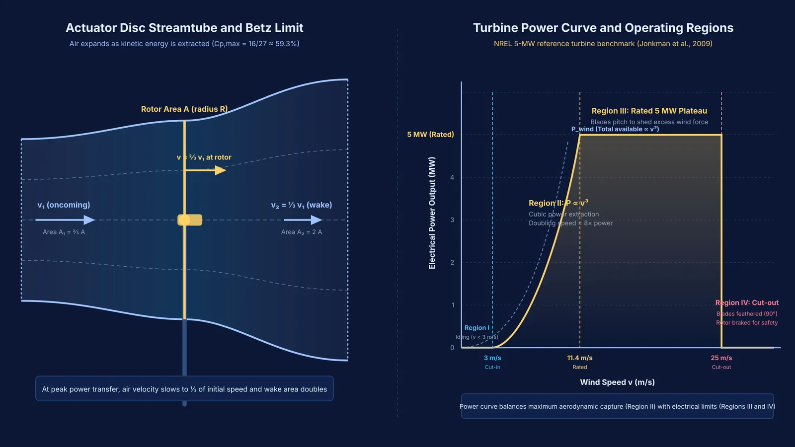
The relationship between wind velocity and power is one of physics' most surprising scaling laws: power grows with the cube of wind speed (v³).
To derive this, consider air of mass m moving at speed v with kinetic energy ½mv², as explained in our guide to kinetic energy and power. Power is the rate at which kinetic energy crosses swept area A. In one second, a cylinder of air of length v and area A passes through the blades. Its volume is Av, giving a mass flow rate dm/dt = ρAv, where ρ is air density (about 1.225 kg/m³ at sea level, standard in National Renewable Energy Laboratory modeling). Multiplying mass flow rate by kinetic energy per unit mass yields:
P_wind = ½ × ρ × A × v³
Velocity enters twice: in the kinetic energy per kilogram (proportional to v²), and in the mass arriving per second (proportional to v). Doubling wind speed from 6 m/s to 12 m/s therefore increases available power by 2³ = 8 times, as documented in the National Renewable Energy Laboratory technical report on reference turbine design.
What is the Betz limit and why can turbines not extract all the energy?
No turbine can harvest all the kinetic energy in wind. In 1920, German physicist Albert Betz proved that no open-flow turbine can capture more than 16/27, or approximately 59.3%, of wind kinetic energy. A historical analysis by Gijs van Kuik in *Wind Energy* (DOI: 10.1002/we.218) notes that this limit was independently derived by Frederick Lanchester and Nikolay Zhukovsky.
This ceiling stems from mass conservation. Capturing 100% of the energy requires bringing air behind the blades to a dead stop (v = 0). But stopped air forms a stagnant barrier, blocking incoming wind and reducing mass flow to zero.
Maximum power transfer occurs when wind slows to one-third of its initial speed, yielding a peak power coefficient Cp of 16/27 (59.3%). Practical drag, tip losses, and generator friction limit modern commercial turbines to peak efficiencies between 35% and 45%, capturing 70% to 80% of the Betz limit, as reported by the U.S. Department of Energy.
Worked example: calculating the power surge from a wind speed change
Consider a turbine with blade radius r = 40 metres in air with density ρ = 1.225 kg/m³, using baseline parameters from the National Renewable Energy Laboratory. Swept area is A = πr² = 3.1416 × (40)² ≈ 5,027 m².
Comparing output between 6 m/s and 12 m/s at an efficiency coefficient Cp = 0.40 (40%), consistent with specifications from the National Renewable Energy Laboratory:
At v = 6 m/s:
Wind power: P_wind = ½ × 1.225 × 5,027 × (6)³ ≈ 665 kW
Output: P_electric = 0.40 × 665 kW ≈ 266 kW
At v = 12 m/s:
Wind power: P_wind = ½ × 1.225 × 5,027 × (12)³ ≈ 5,320 kW (5.32 MW)
Output: P_electric = 0.40 × 5,320 kW ≈ 2,128 kW (2.13 MW)
Doubling wind speed yields an 8-fold surge in electrical output.
Turbines manage this surge along an engineered power curve. In the National Renewable Energy Laboratory reference model, generation starts at a cut-in speed of 3 m/s, plateaus at a rated power of 11.4 m/s where blades pitch to shed excess force, and shuts down at a cut-out speed of 25 m/s to prevent structural damage.
For students tackling numericals on energy conversions and efficiency, the Fermi Problem Library provides worked problems with a step-by-step solver that explains the reasoning rather than printing an answer.


