

On this page
When you study electromagnetic induction, most early problems feature a constant magnetic field and a moving loop. But what happens if the coil is completely still, and the magnetic field itself changes in a wave-like pattern?
This scenario—a stationary coil in a sinusoidally varying magnetic field—is the core principle behind induction heating and transformers. By applying Faraday's law of induction, we can find exactly how much voltage (EMF) is created and how it syncs up with the changing field.
What is the induced EMF when the magnetic field varies sinusoidally?
According to Faraday's law of induction, the induced electromotive force (EMF) in a coil is equal to the negative rate of change of magnetic flux through it.
The magnetic flux (Φ) through a coil of N turns and area A is Φ = NAB cos(θ). If the coil is positioned perpendicular to the magnetic field to capture the maximum flux, the angle θ is 0, so cos(θ) = 1. The flux simplifies to Φ = NAB.
If the magnetic field B varies sinusoidally with time t, we can write it as: B = B₀ sin(ωt)
Here, B₀ is the peak magnetic field and ω is the angular frequency (which relates to the normal frequency f by ω = 2πf).
Substituting this into the flux equation gives: Φ = NAB₀ sin(ωt)
To find the induced EMF, we take the derivative of the flux with respect to time and apply the negative sign from Lenz's law. The derivative of sin(ωt) is ω cos(ωt). EMF = − dΦ/dt = − d/dt [NAB₀ sin(ωt)] EMF = −NAB₀ω cos(ωt)
This tells us that the induced EMF is a negative cosine wave, which oscillates at the exact same frequency as the magnetic field. If you have gaps in your understanding of how trigonometric derivatives link to physics, the Fermi Concept Library contains every concept in physics, chemistry, biology, mathematics and computing, each with its own lesson and its place in the map.
What is the peak value of the induced EMF?
The formula EMF = −NAB₀ω cos(ωt) has a maximum value whenever cos(ωt) is equal to −1.
Therefore, the peak induced EMF (often written as E₀) is: E₀ = NAB₀ω
This equation is a checklist of how to maximise the induced voltage in a stationary coil:
Increase the number of turns (N).
Use a coil with a larger area (A).
Apply a stronger maximum magnetic field (B₀).
Increase the frequency of the magnetic field's oscillation (ω).
Because ω is a multiplier for the entire EMF, a high-frequency magnetic field induces a much larger peak voltage than a low-frequency field of the same strength.
Why is there a phase lag between the field and the EMF?
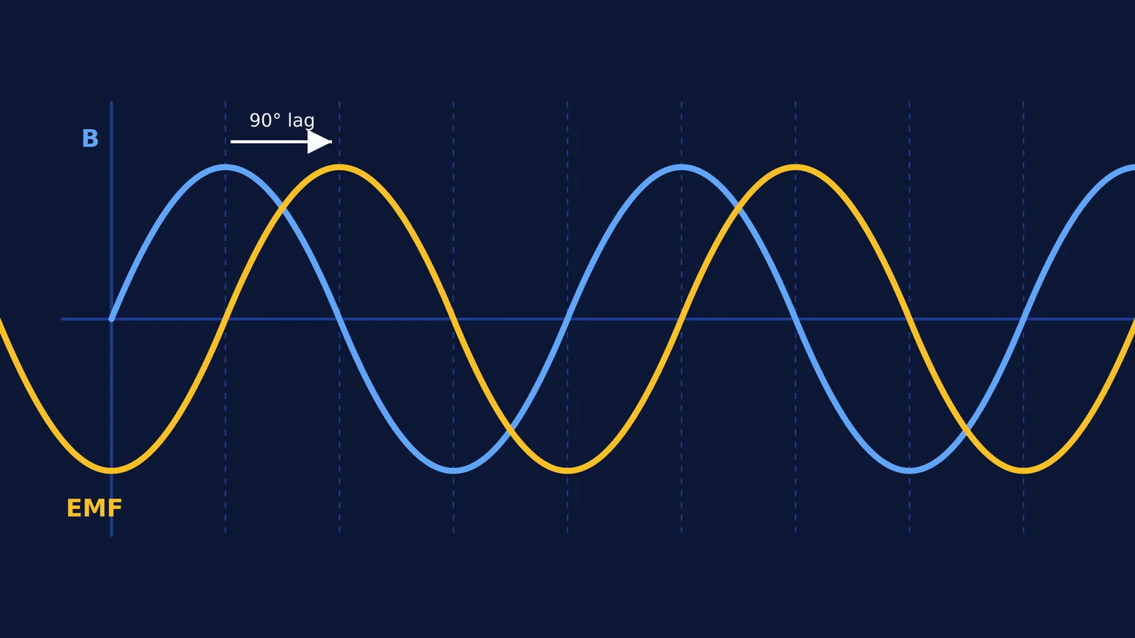
If you plot the magnetic field B = B₀ sin(ωt) and the induced EMF = −NAB₀ω cos(ωt) on the same graph, you will notice they do not peak at the same time.
In trigonometry, −cos(x) is identical to sin(x − 90°). This means we can rewrite the EMF equation as: EMF = E₀ sin(ωt − 90°)
The minus 90° is the phase shift, meaning the induced EMF lags behind the magnetic field by exactly 90 degrees, or π/2 radians.
Physically, when the magnetic field is at its maximum (the peak of the sine wave), it is momentarily flat, so its rate of change is zero. At this exact instant, the induced EMF is zero. Conversely, when the magnetic field crosses zero, it is changing at its fastest rate, so the induced EMF is at its absolute peak. Understanding this timing is crucial for Faraday's and Lenz's laws: finding the induced current direction.
Why does this matter for transformers?
The principle of a stationary coil in a changing magnetic field is the core mechanism behind electrical transformers. An alternating current in the primary coil creates a sinusoidally varying magnetic field in an iron core. Because the secondary coil experiences this changing flux, an EMF is induced across its ends. By choosing different numbers of turns for the primary and secondary coils, a transformer can step up the voltage for efficient transmission or step it down for safe home use.
How do you apply this in a worked example?
Imagine a circular coil with 50 turns and an area of 0.02 m² placed in a magnetic field that varies as B = 0.5 sin(100πt) Tesla.
First, identify the components from the field equation:
B₀ = 0.5 T
ω = 100π rad/s
Next, calculate the peak EMF (E₀): E₀ = NAB₀ω E₀ = 50 × 0.02 m² × 0.5 T × 100π rad/s E₀ = 50π Volts (approximately 157 V)
The full equation for the induced voltage is therefore: EMF = −50π cos(100πt) Volts.
Whether you are analysing a stationary setup like this one or calculating a coil entering a magnetic field: EMF and current graphs, the core principle remains identical: the induced voltage is always driven by how fast the flux changes, not how large it is.


