

On this page
What are cathode rays and how were they discovered?
When nineteenth-century physicists evacuated glass tubes and applied high voltages across sealed electrodes, an unexpected glow illuminated the glass walls. In 1859, Julius Plücker observed these electrical discharges in low-pressure gases, and in 1876, Eugen Goldstein named the invisible emissions streaming from the negative electrode cathode rays.
At atmospheric pressure, gases act as electrical insulators. When gas pressure inside a discharge tube is reduced below 0.01 mm of mercury and a potential difference exceeding 10,000 volts is applied, residual gas atoms ionise. The resulting positive ions collide with the cathode, ejecting electrons that accelerate toward the positive anode. To see how early discharge tubes evolved into modern apparatus, read about William Crookes and glowing vacuum tubes. For students building foundational knowledge across physics and chemistry, the Fermi Concept Library maps every concept with dedicated lessons that place experimental discoveries in their historical context.
What are the key properties of cathode rays?
Decades of systematic laboratory trials established the defining physical properties of cathode rays:
Straight-line propagation: Cathode rays travel in straight lines perpendicular to the cathode surface. Placing an opaque obstacle, such as a metallic Maltese cross, in their path casts a sharp shadow on the opposite glass wall.
Mechanical momentum: Striking the light mica vanes of a small paddle wheel mounted on low-friction rails rotates the wheel along the tube, proving that cathode rays carry momentum and kinetic energy.
Negative charge: In 1895, Jean Perrin collected the rays in an insulated cylinder connected to an electroscope, proving that they transfer a negative electric charge. In an electrostatic field, the beam deflects toward the positive plate.
Heating and penetration: When focused onto thin platinum or gold foil, cathode rays heat the metal to incandescence. They also penetrate thin metal foils before scattering or decelerating.
Fluorescence and X-ray emission: Cathode rays induce bright luminescence when striking zinc sulphide, glass, or barium platinocyanide screens. When high-velocity cathode rays suddenly halt against dense metal targets, they emit penetrating X-rays.
How did J. J. Thomson measure the e/m ratio using crossed fields?
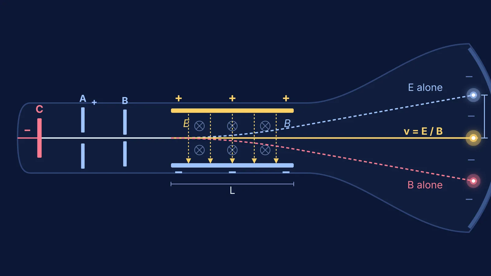
In 1897 at Cambridge University's Cavendish Laboratory, J. J. Thomson designed a discharge tube with crossed fields to settle whether cathode rays were waves or particles. In his *Philosophical Magazine* paper, Thomson placed parallel electrostatic deflecting plates and a transverse electromagnet over the same beam region, creating mutually perpendicular crossed fields.
His measurement followed two coordinated steps:
Velocity selection: An electric field E between plates of length L exerts a transverse electrostatic force Fe = eE on each particle of charge e. A perpendicular magnetic field B across the same zone exerts an opposing magnetic Lorentz force Fb = evB. By adjusting field strengths until the two forces balanced exactly (Fe = Fb), the beam passed through undeflected, isolating particle velocity without needing mass or charge: v = E / B.
Deflection measurement: Thomson then removed the magnetic field, leaving only the uniform electric field E. The constant transverse acceleration a = eE / m causes an exit deflection angle θ ≈ eEL / (mv²). On a fluorescent screen placed at distance D from the centre of the plates, the measured vertical spot deflection y equals (e/m) × (ELD / v²).
Substituting v = E / B into the deflection relation eliminates the velocity term, isolating the specific charge:
e / m = (y E) / (B² L D)
To explore how charged particles curve inside electrostatic fields, see our guide on electron deflection between charged plates, or examine how modern mass spectrometers use a velocity selector with crossed fields.
Why was a universal e/m ratio such a radical discovery?
Before Thomson's measurements, the largest known charge-to-mass ratio in physical chemistry belonged to the hydrogen ion (H⁺). According to the NIST CODATA database, the proton charge-to-mass quotient is approximately 9.5788 × 10⁷ C/kg.
Modern values codified by NIST CODATA place the electron specific charge magnitude at approximately 1.7588 × 10¹¹ C/kg. This value is roughly 1,836 times greater than that of the hydrogen ion. While Thomson's initial 1897 measurements determined an order of magnitude of roughly 10¹¹ C/kg (recorded as 10⁷ emu/g), subsequent refined experiments confirmed this accepted figure.
Crucially, Thomson varied both the cathode metal (aluminium, iron, platinum) and the gas filling the tube (air, hydrogen, carbon dioxide). In every single run, the measured e/m ratio was identical within experimental limits. Because this specific charge never changed with different chemical elements, Thomson deduced that cathode rays are not element-specific gaseous ions, but fundamental subatomic particles—initially termed corpuscles, and now known as electrons—common to all matter.
How do you solve e/m deflection problems in exams?
Competitive exam questions frequently test crossed-field equilibrium and electrostatic trajectory calculations modeled on J. J. Thomson's 1897 experiment. When tackling these problems, apply this 3-step strategy:
Check the balance condition: If an electron beam passes undeflected through perpendicular electric and magnetic fields, apply v = E / B immediately.
Separate horizontal and transverse kinematics: Horizontal velocity vx = v remains constant throughout the flight. Transverse acceleration a = (e/m)E acts only while the charge travels between plates of length L, over transit time t = L / v.
Relate accelerating potential to velocity: If electrons are accelerated from rest across a potential difference V before entering the deflection plates, kinetic energy conservation gives (1/2)mv² = eV, yielding v = √(2eV/m). Substituting this into the transverse deflection equation links deflection directly to the accelerating voltage: y ∝ 1 / V.
Worked deflection example:
An electron beam enters parallel plates of length L = 5.0 cm separated by d = 2.0 cm, across which a potential difference of 200 V is maintained. A uniform magnetic field B = 5.0 × 10⁻⁴ T applied perpendicular to the electric field keeps the beam undeflected. If the magnetic field is removed, calculate the transverse deflection y₁ as the electrons exit the plates. (Use the NIST CODATA specific charge magnitude of e/m = 1.76 × 10¹¹ C/kg).
Calculate the electric field between the plates: E = V_plates / d = 200 V / 0.02 m = 1.0 × 10⁴ V/m.
Determine electron speed from the balance condition: v = E / B = (1.0 × 10⁴ V/m) / (5.0 × 10⁻⁴ T) = 2.0 × 10⁷ m/s.
Find transit time through the plates: t = L / v = 0.05 m / (2.0 × 10⁷ m/s) = 2.5 × 10⁻⁹ s.
Compute transverse acceleration: a = (e/m)E = (1.76 × 10¹¹ C/kg) × (1.0 × 10⁴ V/m) = 1.76 × 10¹⁵ m/s².
Calculate exit deflection: y₁ = (1/2) a t² = 0.5 × (1.76 × 10¹⁵ m/s²) × (2.5 × 10⁻⁹ s)² = 5.5 × 10⁻³ m = 5.5 mm = 0.55 cm. Because 5.5 mm is less than the central clearance of d / 2 = 1.0 cm (10 mm), the electrons exit between the plates safely without colliding with the positive electrode.
When practice questions combine multi-step kinematics with shifting field geometries, the Fermi Problem Library offers worked problems with a step-by-step solver that explains the underlying reasoning rather than just printing an answer.


